Leaderboard
Popular Content
Showing content with the highest reputation on 09/01/2020 in all areas
-
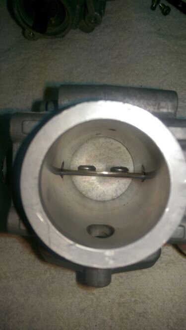
So I've just been rebuilding my throttle bodies due to bush wear and leaking seals. Although this is for the Daytona side flow bodies the top feed bodies are exactly the same in detail. So first thing to do is remove the throttle bodies which requires separating the cross supports on the bike. The top steel support fasteners come out fairly easily but the lower alloy cross brace held by the countersunk 5mm bolts are super hard. Dont even consider removing these without heat and a lot of concentrated heat. You need a fine tip oxy torch with a hard flame. So it needs a lot of heat directly on the head of the screw for longer than is really comfortable. Forget using a small propane torch it wont be enough. Even a soft flame with the oxy isn't enough. You only need to remove 2 screws on one throttle body lower brace as this will allow both to be removed and both ends of the upper steel brace which as I said the screws remove easily.A word or warning or caution here. My advice is to use the heat as described on the L/H throttle body screws only and leave the R/H alone. Reason being is that the aluminium cross brace on the R/H side has been milled to a fairly thin section and can be damaged on the end by the conducted heat. You wont haw any issues on the L/H side as the brace is a much heavier section. After you remove the throttle bodies the shaft is held in buy a circlip on one side. The left needs the throttle cable sector removed first. Dont undo the nut without restraining the cable sector itself so the torque isn't transmitted through the shaft. You also need to remove the throttle plate assy. This is the trickiest part of the job. The 2 4mm screws that hold the throttle plate have the tail end staked. You need to grind the tails off the screws so they can be removed. I did this with a die grinder and a carbon tungsten cutter and reused the screws on one set of throttle bodies but will use new Titanium screws on the other. Mark the throttle plate so you can install it in the correct orientation.(Importanto) Also try and make sure there are no distorted/damaged threads left after grinding off the staking as you dont want to damage the threads in the throttle shaft whilst unscrewing the fasteners. Best way to do this is to grind the screws down to almost flush with the the shaft and carefully remove them. If they jam up a little screw them back in and use a small right angle pick to clean up the distorted thread and try again.The shaft only has a few threads in it so it's important they aren't damaged. It's not as hard as it sounds just take time and caare removing the screws. Here's an image of the completed installation. I'll add an image of the staked screws before grinding later. Here's the circlip with the washer under it and under the washer is the seal. Hears the other side with a new seal installed just for reference. Note the orientation of the seal which looks backwards but this is the way it needs to be. Remember the vacuum is inside and the pressure ( atmospheric) is outside which is opposite to most instillation. Half the original seals were around the wrong way and one was missing altogether on the 2 sets of throttle bodies I have done. Once the shaft has been removed its time to extract the old bushes. I used an old whitworth taper tap because I din't have a 9mm taper. Thread it into the bush about 5 turns and then use a drift from the opposite side on the end of the tap to knock out the bush. I use a piece of wood with a hole in it to support the TB. Here's what you end up with, an old bush on the tap. TB with bush removed. Next up clean out the bushing bore and apply a little grease of your choice in preparation to install the new bush. Here's the new bushes and seals. Bushes are Glycodur brand DU bushes p/n 081008F although any standard DU 8x10x8 bush will be fine. Cost around $2 each. The seals are Yamaha p/n 256-14997-00-(00) at around $3 each. EDIT..... These Viton ones look even better but more pricey. https://ca-cycleworks.com/t-seal.html I made up a simple installation tool to press the bushes in. very simple. Next use the tool to press in the new bush. New bush and seal installed. Repeat for the other side. Refit the shaft and seals in the correct orientation and refit the cir-clip and washer and re fit the cable sector and shaft nut supporting the sector as you tighten the nut. So to install the throttle plate insert it in the correct orientation as you marked it during removal and install the screws loosely. Make sure the throttle plate and shaft is completely closed with the throttle plate against the throttle body bore( back off the idle screw if fitted so the plate contacts the TB bore to align the plate) then tighten the screws. I haven't staked the screws but used blue loctite on them. I've never found a throttle plate screw loose in the 3 sets I've had apart and they dont even use Loctite. The staking isn't to stop the screw loosening only to prevent it coming completely undone, so you can get a turn out of the screws before the staking stops any further rotation. There is a risk in re staking that you might bend or distort the shaft and I'm comfortable with the Loctite doing its job. I have however used some witness marks and can easily check them from time to time but I'm confident it wont be an issue. Later TB's have the screw heads on the upstream side of the throttle plate. Thats it. The only tricky part is die grinding the tails off the throttle plate screws in reality. The rest can be done easily with hand tools and a vice. You now get nice tight shafts which seal well dont drip fuel onto the engine and give a stable idle and easier TPS base setting. Here are some options for the R/H throttle body arm ball fitting. Mercedes but cant remember the p/n. Requires removal of the old ball. Use if ball is worn. Handy bolt on style and works well. There are quite a few of this style available for 8mm ball and 5mm r/h threaded shaft. Plastic/metal and metal with seal. Plenty of choices. Volvo part which has a releasable clip to aid removal. Volvp P/N 946703. $7US each on ebay. Ciao7 points
-
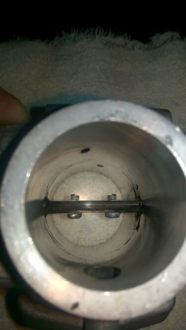
Hi Phil, thanks, a very lucid and detailed explanation. I re-worked the throttle bodies of my Jackal and V11 some years ago, some additional comments based thereupon. This is important, the butterfly valves have edges ground at an angle to fit to the throttle bodies when closed. The original screws block a substantial amount of the cross section, the two pictures (before/after) show the difference. Using flat-headed screws frees up some of the cross section, especially if the screw is selected (or made to fit) to the diameter of the shaft. For those willing to go further, one half of the shaft can be removed. Freeing up even more of the cross section for increased airflow. Cheers Meinolf4 points
-
I have gone to uninsulated butt connectors and heat shrink . This is the only approved method for FoMoco wiring repairs . I have done it for 3 years now and will never go back to anything else . Get this and practice doing it . After talking to smarter people a long time ago , I threw away about 5 lbs. of the Scotch-Lock connectors . P.S. do not modify the factory wiring unless you know what you're doing and why you're doing it . The guy that messed up the original wiring had good intentions . He just knew enough to mess things up . You should be able to get good uninsulated butt connectors and heat shrink w/gooey inside to make repairs . You can buy the good stuff where they sell good stuff .4 points
-
Yep, the green/white power input to Relay#2 is what would come from the 5th pin of Relay#1. Not many micro relays in the world have the rated capacity to handle that current through the weaker NC contact, but your G8HE OMRON will do it. Once that ScotchLok is off, try to make sure it has not damaged the power wire to Relay#1. By design, they cut into the strands.3 points
-
anyone know if the 15RC from a California works for a Lemans? i'm assuming yes, so long as the proper map is uploaded... but maybe i assume wrong.2 points
-
This old post actually has a diagram showing the headlight relay bypassing the starter relay: EDIT: however, that diagram looks very wonky to me... it bears almost no similarity to the factory wiring schematic, so I'm not sure I would trust it as any sort of reference. HOWEVER, if the drawing in that post is meant to illustrate result of modified wiring, then I would be wary that something similar may have happened to Kane's bike, which is to say, I would be cautious "fixing" that one connection on relay #1 without being sure other things weren't shifted around as well. __Jason2 points
-
On the early V11 Sports, the entire load on Relay#2 (including the headlight) is fed through the weaker NC contact of Relay#1. Running a High Current OMRON has not always been a known solution, so these folks just bypassed that function by combining the power to both relays. Relay #1 will no longer be stressed on that contact since it is bypassed. Sure the LED draws less. I am not sure if it is bad for, say, the tachometer to experience that drain from cranking then some kind of inrush current. Or if that inrush current is any higher than the NC contact reconnecting in the unaltered design. Someone else should comment on those ScotchLok connections. I've always heard they are frowned upon. If you were to leave it wired that way, I would think a more positive connection would be desirable.2 points
-
There it is. Some PO, or their "technician" modified the wiring by using that nasty ScotchLok to defeat the 5th pin "load shedding" function and simply connect the power input to Relay#1 with the power input to Relay#2.2 points
-
So well done, Lucky Phil! Just stellar, your documenting this and sharing. This is exactly the kind of thread that belongs in the "How to . . ." sub-forum. Thanks, again, Lucky Phil!1 point
-
No, I have a lathe but I'm VERY ordinary on it. Chucks the house machinist:) Aircraft engineer was my field. Researching parts is where the time goes mainly and it's often many hours involved. Fortunately I also know some very smart and experienced people. My friend told me that the bushes were standard DU steel backed, bronze coated with an additional metal-polymer coating available at any bearing shop. This of course after I'd spent hours in research:) Interestingly the old bushes after removal had a part number on the back and some sort of company logo which I couldn't identify even with a mag glass. So by chance during research I managed to source the company that made the original bushes that Weber used by the numbers and logo together. I figured you may as well use the originals but I have some generic bushes as well that work perfectly fine. The Yamaha seals was just internet research and cross referencing the sizes. The size is quite common for 8mm throttle body shafts it seems. I'm more surprised Yamaha sells them as a spare part. Good one Yamaha. My objective is to show that this can be done at home by anyone with some readily available tools. The Oxy set is the only thing and is important as I mentioned and the screws identified need a quick hit with intense heat. Weber as usual have prioritised nothing coming loose over ease of maintenance which is understandable but it makes removal in situ a real PITA. Ciao1 point
-
1 point
-
AFAIK, no US V11 had oxygen sensors. Pretty awesome SooRoo has found this simple change! Something we would have never discovered in places where the V11 has no O2 sensor . . . (off topic, then: biggest two issues I see missing from your list @Tom in Virginia is CO Fuel Trim zero and TPS baseline. Pretty sure those are on for the SpineRaid TechSession!)1 point
-
I am with docc . If someone else has been fixing things , they have probably f'd with this too . Check everything . Disclaimer : I am not smart , just full of ignorant mistakes and learned from a few .1 point
-
Relay#3 is the least stressed relay in the stack. It is energized by the Neutral Switch so the bike will start and run with the stand down. In gear, the Run Switch gets power through the Sidestand Switch when the stand is up (no relay). Calling Relay#3 the "sidestand Relay" is a misnomer and source of confusion, IMO. The Neutral Light is lit by the Neutral Switch before the relay, so will be lit even though the relay is absent or may have failed. That your bike will start in gear suggests a stuck Sidestand Switch, its wires crushed together (like under the alternator cover), or (perhaps most likely in your case) some PO decided to defeat the switch and hot wired it (twisted the wires together) upstream from the switch. Follow the wiring upstream from the sidestand and look for an ugly blue box (ScotchLok! ).1 point
-
1 point
-
Intense and incredible . Are you a machinist by trade ? How did you find these parts to begin with ?1 point
-
1 point
-
1 point
-
Yeah, those alternate headlamp harnesses with their own fused power and separate relays for hi- and lo- beam were a way to deal with the overloaded relays early on. My Sport has this system, but no longer used since finding a reliable LED headlamp unit. And High Current micro relays (OMRON G8HE). The very first issue my dealer addressed on my Sport (within a couple months) was to send me a larger relay for the #1 position. Later (~2002), Moto Guzzi changed the wiring harness to power Relay#2 from the Ignition Switch instead (like older Guzzis with "Startus Interuptus"®).1 point
-
Thanks for that clarification - I missed that detail and it left me scratching my head. __Jason1 point
-
The number one relay has five active connections. But five prong relays will work in any on the locations. Oh this much more complicated as I read on. Someone hotwired the first two relays. I didn't even understand why or how or what that blue thing is.1 point
-
So, that discussion is about using separate relays and direct wiring for the headlights, but not about the existing relays and how they are wired in the factory harness. That wiring actually bypasses both Relay#1/Start Relay and Relay#2/"Headlamp" Relay to supply power through a dedicated headlamp harness from the battery.1 point
-
1 point
-
Well, you will need to replace the connector that fits into the relay base. Unless it is still part of the wire to Relay2?1 point
-
1 point
-
Or perhaps, when you investigate the relay bases to perform the Kiwi_Roy tightening procedure, you will find someone has pulled that 5th connector from Relay#1 and wired it hot to where it powers Relay#2. Essentially eliminating the weak NC contact/ 5th pin of Relay#1, but leaves all of that load (especially the headlight) on while cranking.1 point
-
How odd! Relay#1 is the Start Relay. When the NO (Normally Open) contact is pulled in with the Start Button, power is sent to the Starter Solenoid. When the contact flips back to the NC (Normally Closed/ "5th") contact, power is directed to Relay #2 for headlights/brake(stop) light/tachometer/warning indicator lights/voltage reference. This effectively defeats all of that power draw during cranking. Does your headlight go out while cranking?1 point
-
I agree with the comments of previous contributors but, to me, the most revealing and interesting bit of information that would seem to help locate the problem is the rather odd phenomenon that the engine does shut down when you pull in the clutch and press the start button. This action energises the starter relay which, apart from putting voltage on the starter motor contactor, it turns off the voltage powering the Lights Relay, thus de-energising the lights, including brake lights, headlights etc while starting. This is fed from Fuse F5, so I would anticipate that pulling out fuse F5 would also shut down the engine when the ignition switch is off. If it doesn't then this would further help locate the cause of the problem as it would imply that there is some connectionbetween the Yellow/Black wire feeding Fuse F5 and the Orange/Blue wire from the ignition switch. So, assuming Fuse 5 does stop the engine, then the fact that pulling in the clutch and pressing the starter also allows the engine to be turned off, then this must imply that there is a spurious connection between this lighting circuit (the Red/Black wire coming out of the Lights relay) and the circuit coming out from contact 3 of the ignition switch, i.e. this fault is bypassing the ignition switch and keeping this contact 3 wire (Orange/Blue) live. You should be able to pin point it further if you see what difference having the side-stand down or not since this connects up the White wire coming out of the side-stand switch that goes all the way back to the Neutral Gear Relay. If the phenomenon occurs with the side stand down, (White wire de-energised) then the location of the spurious connection is more constrained. The Red/Black lighting wire must be spuriously powering the Orange/Blue ignition switch contact 3 wire. These wires do not share the 5-way AMP connector to the RH handlebar controls and front brake so it cannot really occur there. but both wires do share wiring to the the large 12-way Amp connector at the front of the bike powering all the warning lights and instruments. Try putting the headlight on main beam and testing if this allows the ignition switch to stop the engine. If it does, it implies that the spurious fault is on the Lo beam part of the wiring, Green/Grey, that also goes to the 12-way AMP connector. If it doesn't change anything and the engine keeps running then it would imply that the spurious connection is between the Red/Black wire going to the 12-way connector and the Orange/Blue wire also going to the connector. Both these wires come from relays at the rear of the bike so, as previous people have suggested, it could be some kind of wiring harness fault, possibly caused by an overheated wire (probably either the live or neutral wires coming out of the regulator. To my mind having two parallel 15A wires to make up the 30A generator capacity is a fundamental electrical design flaw. It obviously works if the wires correctly share the current but we know that poor charging can often be caused by poor contacts often in the 4-way connector that isn't sealed because it is a spade type (Amp connectors won't take the amount of current). It is at the front of the bike, near the oil cooler and can easily get a bit of corrosion due to water ingress (and salt if you live in the UK and use the bike in the winter). This will cause slightly higher and different contact resistances, the current will not be shared evenly, potentially being taken by only one wire if the contact resistance becomes significant. You won't know its happening but the wire will be overloaded, particularly soon after start-up when recharging currents are 22-25A. This could melt the insulation and cause a faults and spurious connections in other wires. So, if you are lucky you will find the spurious connection at either the 12-way Amp connector at the front end, or at the wiring to the relays, but it may be in the harness in between. At least you know which wires are involved. And this leads me to a suggestion to avoid stripping out the harness. If you can isolate the exact wires that are shorting out by disconnecting them at both ends but still finding that they are connected inside the harness, then keep them disconnected and run a pair of parallel wire between the ends to take their place. You should try disconnecting the 12-way connector and seeing whether your non-stopping problem disappears. If it does then the fault is on the lighting, warning light, instrument side of this connector but if the problem persists then the fault is definitely on the feed-in side of the AMP connector. Also see if de-energising the Lo beam wire makes a difference. Using careful logic is the best way to identify the problem. I hope this is helpful and shows that you should be able to avoid stripping the harness.1 point
-
None of the in tank electronics "spark". If they do, that's badness. And yes, the pump motor is brushless. Edit - I don't think the pump is brushless in early 2000's. The brushless motors are becoming more common. I know this because my company build the controller chips used for these motors. (A good business for us!). It's the concentration of the fuel vapor that prevents explosions. From Google - "The reason electric, tank- mounted fuel pumps do not cause explosions is that the concentration of fuel vapors is too high to allow an explosive mixture. The volatile (which in this context refers to a tendency to evaporate) nature of gasoline causes fuel vapors to take up any empty space as the fuel tank is emptied. Even if you completely empty a tank, open its access ports, and allow it to sit open, the concentration of vapors INSIDE the tank will still be too high to explode. Now, OUTSIDE the tank is a different story, and for this reason, one must use caution when performing any sort of repair or maintenance to a fuel tank, regardless of the type of pump used on the vehicle."1 point
-
Okay, sorry for not getting back to this earlier - but got caught up with the usual stuff. So following the two adaptation rides under 3000rpm - I went on a ride into the city of some 45 minutes with plenty of stoplights, roundabouts etc. the bike was an absolute joy - smooth, stable tempo with every manoeuvre, gear change. Then I took the bike out beyond the suburbs to give it some gas. Perfect. What was most notable, rolling off the throttle the bIke has lost all its pops & burbles emitted from the M4’s. Zero. All revs, all gears, downhill coasting from high to low revs - nothing. Buttery smooth. Even after services from various renowned Guzzi mechanics - the bike has never been better. The new Bosch LSH24 0258003805 sensor cost €41.22 - sent from AutoDoc Germany to my friend in the UK for another €20.64 postage & 20% VAT. Friend posted it to me for around £13 all up. (AutoDoc doesn’t send items outside EU to Australia). Anybody who has an O2 equipped V11 with the 15RC ECU should swap in a quality LSH24 sensor. It is such an inexpensive item, easy to swap over - don’t bother with any ECU modifiers until this is done first. Brilliant upgrade. My bike has literally been reborn. Safer, smooth & vigorous. In my view - there’s nothing wrong with the Magneti Marelli 15RC ECU - any suggestion to disable O2 sensor V11’s has been made redundant. The ECU has simply been limited by GIGO - garbage in garbage out. Get rid of those slow crappy old LSH15 sensors! Finally, I wish to give all credit to the post by MotoUbe on Anima Guzzista forum. Thanks to Ube - my bike is as comparably smooth to any Honda or BMW. Cheers fella’s! 👍😎1 point
-
Okay... before I go further - on my bike the O2 sensor site was relocated on the left header just in front of the oil dipstick when a MassMoto X-over was installed. The existing O2 sensor was just rerouted to that location. Whilst my bike was noticeably freer-breathing from mid revs all the way to redline and my riding habits had shifted up the range by some 500-1000rpms - what should be noted was that there was no real actual change to my bikes modus operandi style in the low range. There was that occasional fart, sometimes a stumble, a miss... all the usual things that’s inherent in our V11’s character. However, after translating Ube’s 2006 posting recommendation I set to sourcing & pricing up the genuine Bosch LSH24 sensor identified as the LS3805 aka 0258003805. Removing the existing sensor it was a surprise to find it was an NTK OZA341-BB1 sensor. More research subsequently revealed this was the NTK manufactured equivalent to Bosch‘s LSH15 calibration curve. After install for the first two rides on seperate days an adaptation procedure was followed: 1. Start engine & allow to idle for 5 minutes. 2. Drive vehicle for 5 minutes between 20 & 30 MPH. Do not allow RPM’s to exceed 3000 RPM’s. 3. Drive vehicle for 15 minutes between 40 & 60 MPH. Do not allow RPM’s to exceed 3000 RPM’s. 4. Stop vehicle & allow to idle for 5 minutes. (It’s late - be back tomorrow... 💤)1 point
-
Curious what’s up with Dietcokeman. Always a bit un-nerving when one of us puts his V11 up for sale....0 points

