Leaderboard
Popular Content
Showing content with the highest reputation on 09/02/2020 in all areas
-
The 15RC ECU is used on O2 sensor equipped V11’s. The 15RC hardware also was used on later Breva’s, Nevada’s, Griso’s & I think the early Stelvio’s - with only the installed software mapping being specific to each model. However Tomchri, just to clarify there is nothing too slow with the Magneti Marelli 15RC ECU - only the original spec LSH15 sensor slow calibration curve input wasn’t able to keep pace with what the 15RC ECU needed to produce a smooth, stable closed loop running state. The LSH24 sensor calibration curve is 10x faster - therefore the fuelling is more accurate - the slow LSH15 sensor input influenced the lurching struggle from too lean, to too rich, back to too lean, again back to too rich ad nauseam... whilst in closed loop range. In fact, whilst the LSH24 is 10x faster - it’s improved speed still can’t match the 15RC’s ECU’s inherent output capability. In fact, any ECU is enhanced by having an O2 sensor to provide feedback input - this enables it to check & analyse that what it is doing (commands) is accurate in accordance to its programming parameters. However, most factory programs in closed loop have just been designed for required emissions & fuel economy. But then again if dyno mapped this emphasis can be modified for whatever the user wants. Read up on Lambda tuning. Whether your bike has a O2 sensor or not - the first thing dyno tuners do is whack a wideband sensor up the pipe to get that essential O2 feedback. But if your bike doesn’t come equipped with O2 - just crack open another IPA & don’t worry ‘bout all this palaver... Only on those models subject to complying with the Euro emission requirements laws.3 points
-
I also have one on the lift table. Roll the bike on and it stand by itself. Then you can leisurely put the straps on. You can pull the front part off with the bike on it if you need to remove the front wheel. I use a center stand for the bikes that have one or a flat jack for the Guzzi.2 points
-
The 10-way is strapped to the down-frame tube under the tank but near to the steering head bearing. I think the 12-way is somewhere close, either to the 10-way or nearer to the instrument panel. I can't be too certain as my V11 was modified by Ghezzi Brian and had a new dashboard and headlights but looking on the parts list diagram, there seem to be two large connectors (the 10 and presumably the 12) in similar positions which look like being near the steering head bearing Your further diagnostic tests are very interesting particularly the fact that the parking and direction indicators are not working. This may just be collateral damage if something has overheated or broken/fused. I'm assuming that you checked Fuse 6 and 7, that powers these two functions, and they are good. What would also be interesting to know is whether if you remove fuses 6 and 7, if with the ignition turned ON, you can detect 12 V on one side of both these fuses. If you can't then there is a problem, either in the ignition switch or between the ignition switch, contact 2 (Yellow/Red) and these fuses that it feeds directly. If you do detect 12V on one side of both fuses then the fault is obviously downstream of the fuse but I'm struggling to see a common failure mode that would affect both Parking and direction indicators at the same time as once the power splits through fuses 6 and 7, the parking light and the direction indicator wiring looks to me to be on separate circuits unless the fault is on a common neutral wire. Something else you should be aware of is that virtually all the black neutral wires that go back to the -ve terminal are not shown on the wiring diagram, presumably to help simplify an already overcrowded diagram. But they do exist. Don't be fooled by all the little earth symbols that appear to show that the -ve side of components are earthed locally and return through the metal frame; they don't, these earth symbols really mean that a black wire runs from this point back to the battery -ve terminal. On my bike (Cafe Sport >=2004) the only current that comes to the battery via the big frame strap connected to the crank/gear case is the current from the starter motor, which is really odd as this is one of the few earth wires that is specifically drawn on the diagram!. So in practice there are dedicated black neutral/earth wires for everything and we often can't see whether any of these neutral wires are shared between (say) the parking light and the direction indicators. However, in this case it does look as though the Black wire of contact 4 in the 4-way Amp connector near the instrument panel, takes a single neutral wire back, but it also earths all the instrument lights and speedo/rev counter lights as well as the headlights, so because you said the headlights work, I think this precludes the fault being in this neutral wire back to the battery. So, I'm still of the opinion that for the clutch starter button to de energise contact 3, the Orange/blue wire that comes from the Ignition switch, that should be turned off when you switch off, but doesn't, then this wire must be being energised by either the Red/Black wire from the Lights mini-relay (that gets turned off when you press the starter with the clutch held in). This is the only way that power via Fuse 5, which is directly connected to the battery, can keep the circuits that should be switched off, live, but get switched off by pressing the starter. So, the fact that the parking and direction lights also don't work seems to me to indicate a wiring harness fault that has broken the common Yellow-red wire feeding fuses 6 & 7 but has also melted the insulation on the Red/Black wire and falsely connected it to the Orange/Blue wire. I'd advise trying to confirm this by isolating the wires at the connectors they go to and testing for continuity or for short circuits. I must admit i was hoping that with sufficient logic I could pinpoint the failure point more exactly, but given this other problem, I think the most likely cause is by a major harness failure, due to an overheated generator live or neutral wire. Do check, clean and grease the 4-way connector near the regulator to avoid any future repairs going the same overheated way. Repairing may be more complicated, but if you can isolate the ends of these wires, prove to yourself that these have failed open- and short-circuit as suggested, then, short of buying a new harness or stripping and repairing the old one, then it ought to be possible to isolate these wires and run a set of new ones to the various end point connectors, sleeve the wires together and tie it neatly with cable ties in parallel to the main harness. Best of luck. Given my experience of2 points
-
John....if you had a high quality wheel chock, you could take all of the pressure off the side stand while keeping it vertical and Bev could be drinking a cool one instead of holding the bike for you! I always park the Scura in the chock just as a safety precaution rather than leaving it on the side stand.2 points
-
No, I have a lathe but I'm VERY ordinary on it. Chucks the house machinist:) Aircraft engineer was my field. Researching parts is where the time goes mainly and it's often many hours involved. Fortunately I also know some very smart and experienced people. My friend told me that the bushes were standard DU steel backed, bronze coated with an additional metal-polymer coating available at any bearing shop. This of course after I'd spent hours in research:) Interestingly the old bushes after removal had a part number on the back and some sort of company logo which I couldn't identify even with a mag glass. So by chance during research I managed to source the company that made the original bushes that Weber used by the numbers and logo together. I figured you may as well use the originals but I have some generic bushes as well that work perfectly fine. The Yamaha seals was just internet research and cross referencing the sizes. The size is quite common for 8mm throttle body shafts it seems. I'm more surprised Yamaha sells them as a spare part. Good one Yamaha. My objective is to show that this can be done at home by anyone with some readily available tools. The Oxy set is the only thing and is important as I mentioned and the screws identified need a quick hit with intense heat. Weber as usual have prioritised nothing coming loose over ease of maintenance which is understandable but it makes removal in situ a real PITA. Ciao2 points
-
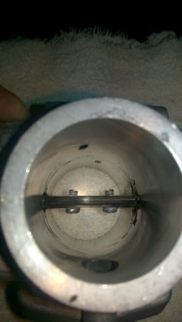
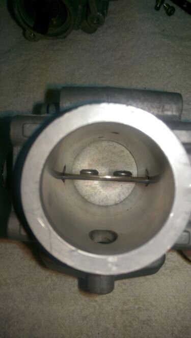
Hi Phil, thanks, a very lucid and detailed explanation. I re-worked the throttle bodies of my Jackal and V11 some years ago, some additional comments based thereupon. This is important, the butterfly valves have edges ground at an angle to fit to the throttle bodies when closed. The original screws block a substantial amount of the cross section, the two pictures (before/after) show the difference. Using flat-headed screws frees up some of the cross section, especially if the screw is selected (or made to fit) to the diameter of the shaft. For those willing to go further, one half of the shaft can be removed. Freeing up even more of the cross section for increased airflow. Cheers Meinolf2 points
-
About a week out and I see I started the Sport's shakedown three months ago and have ridden it over 2700 miles. About as ready as it can possibly be and properly separated from the Waddington Effect (unwanted outcomes from my messing with it ). I told a buddy that if I didn't saddle up and head out next week she would probably sprout a cortex and leave without me! SpineRaiders are looking to number 10-14 for this S'xteenth South'n. Y'all ride well, ya hear?1 point
-
I think all the riding you do has kept it off the side stand just as much.1 point
-
Makes me wonder if keeping my Sport on the lift in the chock all the time has helped spare my sidestand switch . . .1 point
-
I have the Condor version, two of them, and the Harbor Freight version bolted to the lift table. Invaluable for stationary work and for transport. This thing will vigorously hold a bike vertical without straps, though I do use 2 straps in the trailer. When I pulled my engine, the front tire rested in it, with 2 ratchet straps (in the rafters) lifting the rear.1 point
-
For us more frugal Guzzi owners. https://www.harborfreight.com/1800-lb-capacity-motorcycle-standwheel-chock-61670.html1 point
-
My 03 Rosso Corsa has a 02 sensor, not connected since there is a 15M ECU onboard,, with great mapping. She runs very good, sometimes somedays, she has to open her mouth a little bit, tiny sneeze, hick, nothing serious. Since I have a 15RC Cali ECU on the shelf, out of curiosity I will install a new Bosch 02 sensor and the 15RC, and see what happens ? Cheers tom.1 point
-
Those Baxley sport chocks are nice. I have one, but wouldn't mind having 1 (or 2) more. It was super-handy back when I used to do track days, both for loading the bike on the (rental) trailer, and for use in the paddock (because my sidestand would be removed due to dragging on the track). And if you use them to keep the bike upright, you may find you have more room in the garage than you used to __Jason1 point
-
I would think it can be done. But I am not sure how hard it will be. Without additional mods to address seating position I am not sure it is worth the effort. Todd at GuzziTech is very fond of doing stuff like that to Guzzi's like that. To me it is lipstick on a pig, as you say. I would just enjoy that for what it is, a surprisingly capable cruiser. And I am not looking at your butt.1 point
-
"The 15RC ECU is used on O2 sensor equipped V11’s." So, even if not O2 sensor equipped, if a 15M/non-O2 sensor bike had aftermarket exhaust with sensor bung, and added the dongle (ran the wiring to a sensor, and plugged into the bung), the RC should work? Partly curiosity, and partly because i'll be playing with ECU and map options on the "other" V11 in the shop this winter (as mentioned in our PM)1 point
-
1 point
-
No.. they are pretty busy. I’m still waiting on the front splitter for my Benz. This weekend I’m sending a bunch of stuff to them, I’ll ask.1 point
-
I have a 15M.C3 labeled for a Cali S in my parts bin. It came to me installed on a great running '03 Rosso Corsa with Mistral crossover and MG Ti cans. The bike previously owned by a former forum member. So I have to assume it was re worked somehow..... Or interchangeable?1 point
-
I am with docc . If someone else has been fixing things , they have probably f'd with this too . Check everything . Disclaimer : I am not smart , just full of ignorant mistakes and learned from a few .1 point
-
I agree with the comments of previous contributors but, to me, the most revealing and interesting bit of information that would seem to help locate the problem is the rather odd phenomenon that the engine does shut down when you pull in the clutch and press the start button. This action energises the starter relay which, apart from putting voltage on the starter motor contactor, it turns off the voltage powering the Lights Relay, thus de-energising the lights, including brake lights, headlights etc while starting. This is fed from Fuse F5, so I would anticipate that pulling out fuse F5 would also shut down the engine when the ignition switch is off. If it doesn't then this would further help locate the cause of the problem as it would imply that there is some connectionbetween the Yellow/Black wire feeding Fuse F5 and the Orange/Blue wire from the ignition switch. So, assuming Fuse 5 does stop the engine, then the fact that pulling in the clutch and pressing the starter also allows the engine to be turned off, then this must imply that there is a spurious connection between this lighting circuit (the Red/Black wire coming out of the Lights relay) and the circuit coming out from contact 3 of the ignition switch, i.e. this fault is bypassing the ignition switch and keeping this contact 3 wire (Orange/Blue) live. You should be able to pin point it further if you see what difference having the side-stand down or not since this connects up the White wire coming out of the side-stand switch that goes all the way back to the Neutral Gear Relay. If the phenomenon occurs with the side stand down, (White wire de-energised) then the location of the spurious connection is more constrained. The Red/Black lighting wire must be spuriously powering the Orange/Blue ignition switch contact 3 wire. These wires do not share the 5-way AMP connector to the RH handlebar controls and front brake so it cannot really occur there. but both wires do share wiring to the the large 12-way Amp connector at the front of the bike powering all the warning lights and instruments. Try putting the headlight on main beam and testing if this allows the ignition switch to stop the engine. If it does, it implies that the spurious fault is on the Lo beam part of the wiring, Green/Grey, that also goes to the 12-way AMP connector. If it doesn't change anything and the engine keeps running then it would imply that the spurious connection is between the Red/Black wire going to the 12-way connector and the Orange/Blue wire also going to the connector. Both these wires come from relays at the rear of the bike so, as previous people have suggested, it could be some kind of wiring harness fault, possibly caused by an overheated wire (probably either the live or neutral wires coming out of the regulator. To my mind having two parallel 15A wires to make up the 30A generator capacity is a fundamental electrical design flaw. It obviously works if the wires correctly share the current but we know that poor charging can often be caused by poor contacts often in the 4-way connector that isn't sealed because it is a spade type (Amp connectors won't take the amount of current). It is at the front of the bike, near the oil cooler and can easily get a bit of corrosion due to water ingress (and salt if you live in the UK and use the bike in the winter). This will cause slightly higher and different contact resistances, the current will not be shared evenly, potentially being taken by only one wire if the contact resistance becomes significant. You won't know its happening but the wire will be overloaded, particularly soon after start-up when recharging currents are 22-25A. This could melt the insulation and cause a faults and spurious connections in other wires. So, if you are lucky you will find the spurious connection at either the 12-way Amp connector at the front end, or at the wiring to the relays, but it may be in the harness in between. At least you know which wires are involved. And this leads me to a suggestion to avoid stripping out the harness. If you can isolate the exact wires that are shorting out by disconnecting them at both ends but still finding that they are connected inside the harness, then keep them disconnected and run a pair of parallel wire between the ends to take their place. You should try disconnecting the 12-way connector and seeing whether your non-stopping problem disappears. If it does then the fault is on the lighting, warning light, instrument side of this connector but if the problem persists then the fault is definitely on the feed-in side of the AMP connector. Also see if de-energising the Lo beam wire makes a difference. Using careful logic is the best way to identify the problem. I hope this is helpful and shows that you should be able to avoid stripping the harness.1 point
-
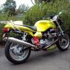
I don,t have any good pictures of My R.Corsa with the DyMag Magnesium wheels on her at the moment but this is one of her from a couple years ago when she was a little dusty ..still looks the same except cleaner and with the oem rear fender back on now.1 point


