

Mechanism
-
Posts
20 -
Joined
-
Last visited
-
Days Won
1


Mechanism's Achievements
Guzzisti (2/5)
34
Reputation
-
ANSWERED Advanced troubleshooting (ECU failure?)
Mechanism replied to Mechanism's topic in Technical Topics
To think that most of my country actually IS below sea level 😉 -
ANSWERED Advanced troubleshooting (ECU failure?)
Mechanism replied to Mechanism's topic in Technical Topics
Exactly. But this buys me the time to get a really nice one, and have it flashed and "plug and play ready" in the future. Many thanks for your support! -
ANSWERED Advanced troubleshooting (ECU failure?)
Mechanism replied to Mechanism's topic in Technical Topics
Still have to try if Guzzidiag connects. But very confident it will work again. Also noticed the time between turning on ignition and priming of the fuelpump has been reduced. It's instant now, but used to take 1 or 2 seconds before. -
ANSWERED Advanced troubleshooting (ECU failure?)
Mechanism replied to Mechanism's topic in Technical Topics
When I bought it 8 years ago, the bike looked like it had been under water. So I'm not surprised to say the least. What is surprising, is that the corrosion forms an edge exactly on a quarter if the print. As if it was physically dipped in water. I started her up yesterday evening and she runs like a sewing machine again. Very happy! -
ANSWERED Advanced troubleshooting (ECU failure?)
Mechanism replied to Mechanism's topic in Technical Topics
You mean the second one from top left? It's the one I had my doubts about.. But the print burnt off so I have no idea what It's supposed to be. -
ANSWERED Advanced troubleshooting (ECU failure?)
Mechanism replied to Mechanism's topic in Technical Topics
To clean the PCB I used Isopropyl alcohol, a very soft toothbrush and before everything dries a modest rinse with demineralized water (to move all that oxidation residue off). Then make sure the board is completely dry before testing. -
ANSWERED Advanced troubleshooting (ECU failure?)
Mechanism replied to Mechanism's topic in Technical Topics
After a good clean, we can see the components have not actually been burnt, but they've been hot. I connected the board to the bike very carefully and finally, the fuelpump primes again and there is power to the coils as well. Now to stick everything back together and hope it will keep working!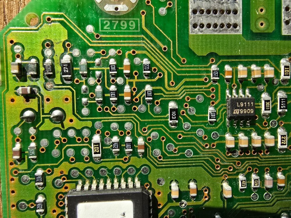
-
ANSWERED Advanced troubleshooting (ECU failure?)
Mechanism replied to Mechanism's topic in Technical Topics
But after turning it over, I noticed a bunch of oxidation connecting the traces on the board. The components close to the corner have been visibly hot because of this.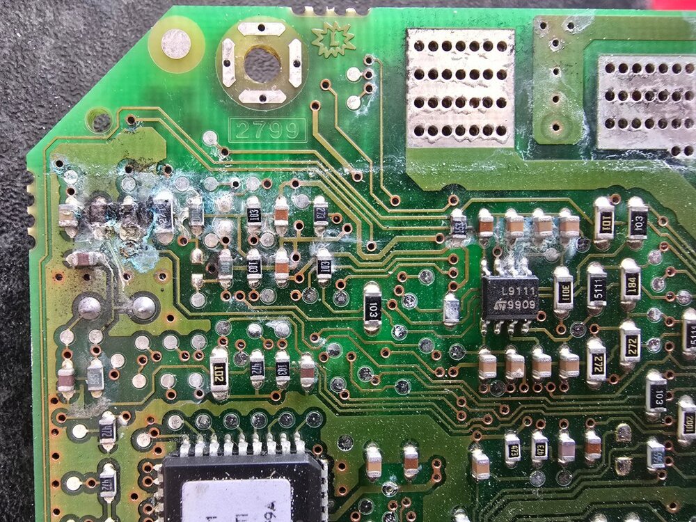
-
ANSWERED Advanced troubleshooting (ECU failure?)
Mechanism replied to Mechanism's topic in Technical Topics
I hope this serves someone in the future, as the forum has served me for years. After removal of the ECU lid we see a nice clean print: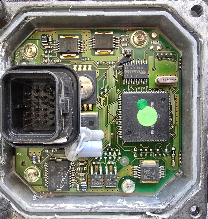
-
ANSWERED Advanced troubleshooting (ECU failure?)
Mechanism replied to Mechanism's topic in Technical Topics
Sooo guess what.. I put the ECU in the oven for an hour at 100 degrees C. Took it apart, cleaned the entire (heavily oxidated) print with Isopropyl alcohol and dried it. Connected the bare print to the loom, ignition on... > priming procedure > power to coils! Yesyesyesyes! Now to reassemble everything and hope it's not a case of 'intermittent ECU'. Will post some 2x4 pixel pictures of this endeavour as soon as possible 😁 -
ANSWERED Advanced troubleshooting (ECU failure?)
Mechanism replied to Mechanism's topic in Technical Topics
I have been a naughty boy and took the ECU apart. I'll start with a much needed cleaning and then hope we have some PCB experts here that know what components have been fried due to oxidation between the traces. Once again: I greatly appreciate all the help! -
ANSWERED Advanced troubleshooting (ECU failure?)
Mechanism replied to Mechanism's topic in Technical Topics
It was running great at the first startup after winter. One week later I'm getting ready for my first actual ride of the year, no fuel and spark. Bike has not moved an inch in between. I may have to start a seperate topic alltogether. As far as I know, all IAW 15M ECU's are interchangeable, as long as you put the V11 software / mapping on it (which I can't, because I hate programming stuff). But if that's true I can get a Ducati 15M ECU for small change, in stead of the exact right V11 one for a sh*tload of money.. And then find someone that can flash a V11 map on it. -
ANSWERED Advanced troubleshooting (ECU failure?)
Mechanism replied to Mechanism's topic in Technical Topics
I ran out of time. Hope to test the rest of the ECU plug shortly. Might as well start looking for a fresh ECU. They are few and expensive out here. And then there is the issue that nearly no setting was original on the current ECU. Expecting a long road to the V11 getting it's roar back. -
ANSWERED Advanced troubleshooting (ECU failure?)
Mechanism replied to Mechanism's topic in Technical Topics
Pin 19 to ground makes the relay switch and turns on the fuelpump. Starting to dread a failed ECU.. 😐 My compliments for your stellar support so far. This is incredibly helpfull, kudos mate. -
ANSWERED Advanced troubleshooting (ECU failure?)
Mechanism replied to Mechanism's topic in Technical Topics
The fuse feeds #4 with a white/green wire. The second prong is two brown/white wires, one leading to relay #5, the other into the loom. When I turn the ignition on, relay #4 switches and sends power to prong #2, the brown/white wire on relay #5 is energized, but #5 does not switch. I switched the (new) relays around and the issue stays the same.


