audiomick
-
Posts
2,507 -
Joined
-
Last visited
-
Days Won
50
Content Type
Profiles
Forums
Events
Gallery
Community Map
Everything posted by audiomick
-
Thanks docc. So, terminal to the back of the bike, and positive on the left from the rider's perspective.
-
Daniel Graig. The old, familiar story, but in "modern". I read about that in another forum. Apparently the hazard warning goes off under very heavy braking, but can't be switched on manually. Curious...
-
Yes. Don't know where it goes yet, I'll have to have another look to find that out. I assumed it was standard something or other, as the pinkish sleeve on it is the same as the other thick cable that is connected to the + terminal. Might be a mod, though, I suppose. PS: can someone post a photo of a standard, or near standard, battery? I gather mine is not in the same orientation as a standard one. Knowing which way around it was mounted originally, and where the + and - terminals were, might help me understand what has been done to the wiring on mine.
-
I find it interesting that they quote "Maximum Switching Power 350 W" (power rather than current). Given that, they are a little inconsistent (I think) by not quoting a voltage for the maximum continuous current. Note that there are voltages given in the contact ratings. I consider it impossible that the maximum current could be the same at any voltage, but I might be wrong. That they specify maximum switching power allows the assumption that a voltage other than 12V could be switched by the relay. Further up I linked to this: https://en.wikipedia.org/wiki/Electric_power where we can see that p = VI, i.e. power is the product of Volts x current. We are talking about motorcycles with a nominal (there's that word again...) voltage in the wiring system of 12 V. That means that, according to the specification of 350W switching power, the relay can safely switch 29,17 A. at the nominal 12 V. As we all know, in a healthy electrical system on a motorcycle the voltage is more like 12.8 V or so, so the real world current that can be safely switched is slightly lower. That this figure is lower than the the continuous carrying current should be no surprise, as we had already established further up that it is generally the case that the "carry" current is higher than the "switching" current. If we consider other voltages and the specification of maximum switching power, then the relay can safely switch anything between 350 A @ 1V to 1A @ 350V. Theoretically, at least. Some more maths: Take the spec 1C : NO 30A@ 14V DC. 30x14= 420 Watt. go back to the nominal 12V in the electrical system: 420 / 12 = 35 which is the stated continous current. Once again, I think they are a bit inconsistent in those specs, i.e. jumping around with the voltages they are assuming, but I'm guessing. Anyway, on the basis of those specs I would assume a safe switching current on a motorcycle of around 30 A., and a safe continuous (carrying) current of 35 A as stated on the spec sheet. If the relay gets really hot, those figures will both be lower, but I as already mentioned, I don't think the relays are likely to get that hot on a V11.
-
Moto Guzzi V100 Sport Tourer: water cooled, 120 HP (26th of August 2021)
audiomick replied to p6x's topic in Newer models
I've seen quite a number of you tube videos that were claiming to be "sound checks" for some vehicle or other. The idea that one can get a realistic idea of what something sounds like from a video that was recorded by a gopro, or better still a mobile telephone, that was then posted on the internet to be listened to on computer speakers, or maybe even a mobile telephone, is simply absurd. -
I had a very good look at all of that, and I'm certain that the cable from the + terminal is not connected to the bolt behind the battery. I'll have another look now that you have all made me uncertain, but... What I saw was the "monstercable" with the connector with the yellow insulation that is connected to the - terminal definitely goes to that bolt. On the photo, one can see the same type of terminal at the bolt. That is the other end of that wire. There is also a connector on there that seems to be part of the original loom. Also, there is a cable that goes to the - side of the accessory socket that is installed in the fairing. If a cable from the + terminal were also connected to that bolt, the battery must already be short circuited to death. It isn't, so I am assuming I followed the wires correctly.
-
a P.S. to the last post: I spoke to my electronic technician colleague again today. He confirmed those assumptions, and went on to say that for our application, pretty much only the stated switching current is directly relevant.
-
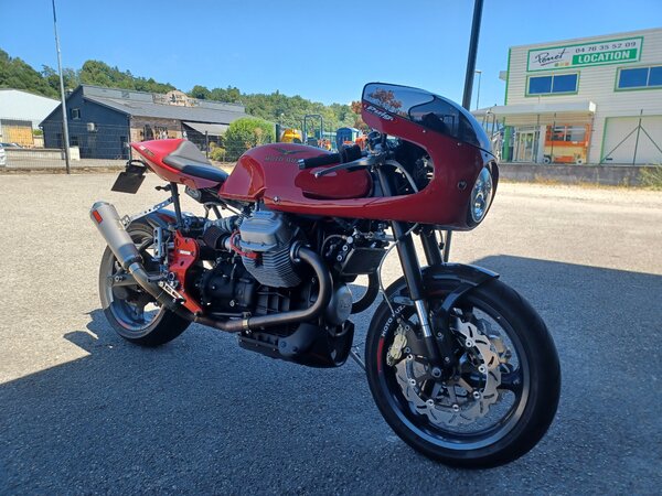
 That's a very pretty bike.
 -
-
Moto Guzzi V100 Sport Tourer: water cooled, 120 HP (26th of August 2021)
audiomick replied to p6x's topic in Newer models
That calling a you tube video a "sound check" is completely absurd. The mufflers look pretty tidy, though. -
Days like this....
audiomick replied to guzzler's topic in Special place for banter and conversation
Almost always, in my experience. -
more thoughts, which may or may not be useful. The relevance of the "maximum temp." specs have been floating around in my head all day. This confims what I already knew, i.e. that the resistance of a metallic conducter increases with increasing temperature: https://www.toppr.com/ask/question/why-does-resistance-of-a-metallic-conductor-increase-with-increase-in-temperature/ The relevant temperature seems to me to be the temperature of the coil. Given that the coil presents a resistance to the volts applied to it, it is going to get warm when it is activated. A resistor (in this case the coil) always gets warm when current passes through it. Something that is warm or hot is at a higher energy level than something that is cold, so the heat in the relay from the coil will be trying to get to the cooler air around the relay. Energy always travels from the higher state to the lower state. Therefore the ambient temperature is relevant to the operation of the coil. We already had made the point that the coil needs more volts to activate the relay when it gets warmer. If we take it as given that the available electrical potential (volts) is a constant, then the various formulae show that the coil is going to exert a weaker pull when it gets warmer. Power = volts x current https://en.wikipedia.org/wiki/Electric_power Volt is constant, so power is reduced when current is reduced Current = volts divided by resistance https://en.wikipedia.org/wiki/Ohm's_law so the higher the resistance, the lower the current. i.e. the warmer the coil gets, the less "pull" it can generate to acivate the relay. Secondary to that, the load contact, i.e. the contact that the relay is making, is also a resistance. Contacts always are. If the relay is switching close to or over its rated current, this contact is also going to be getting warm, and that heat is most likely adding to the heat in the coil because they are all in a tiny little box together. When the coil gets too warm, and "weak" as a result, it seems to me to be likely that the contact that the relay is making is likely to start jittering, or even open slightly and stay that way. This would lead to arcing, as has been referred to earlier, with the result that the load contact would either weld closed or erode away into uselessness. At this point, the relay has failed. Having said all that, I seriously doubt that the ambient temperature around the relays in a V11 would even get close to the numbers I have been seeing in spec. sheets (typically 85°C and 125°C). I have an idea how I might be able to check on that, but I'll get back to that sometime when I have had a chance to try it out. Anyway, I tend towards the following conclusion: We have discussed the lower permissable switching current at higher temperature ( e.g. 20 A. @ 85°C when the nominal switching current is 35 A.). Obviously the highest possible switching current is desirable, but I don't think that the maximum temperature is likely to be reached in our application. Therefore, I don't think we need to get leery about those "maximum temp." specs. . If anyone can see a fault in the logic, please say so.
-
Yes, I considered keeping mine for just that purpose. I didn't, because we already have far too much stuff lying around. But I have photos.
-
 Without seeing it "in the flesh", I think I'd be inclined to file out the two holes in the gasket right at the top, i.e. make them a bit oval downwards. From what I can see in that picture, the distortion seems to result from those two holes forcing the upper section of the gasket too far downwards. Annoying when a part doesn't fit right...
 -
I can see that applying to paper gaskets, but I can't imagine that it would work for one with a metal core.
-
Shoei X11. Hmm, I believe that was the helmet I was wearing when I crashed in 2017. Mine looked pretty similar to the picture in that report. A couple of millimetres of material ground off on the chin piece almost exactly on the same place as his, and massive scratching on the visor. As the man wrote, a full-face helmet is the only way to go.
-
Days like this....
audiomick replied to guzzler's topic in Special place for banter and conversation
Fantastic. It's good when it all works out. -
docc, I just noticed that I didn't respond to this That has been discussed in "Best Relay", I think Fuses all look ok. Yes, the wiring has been changed. However, the bolt holding several cables together behind the battery is not an unshielded postive, but rather a "common ground", i.e. it connects a cable from battery minus with a connector out of the loom and an addition that supplies the negative contact to an accessory socket up behind the instruments. So it is not dangerous, even if I am not completely happy with the solution.
-
That would make a certain amount of sense, but here it would also mean you (the bike) would fail the bi-annual roadworthy inspection. There has to be a switch, or a side-stand that folds itself up when the bike is stood up.
-
Hold the presses. I think that is turned around. It should be "resistive load" and "resistance". Resistance is how much a component resists the flow of current through itself. As noted earlier, work done (power in Watt) is the product of Volts and resistance. Resistance seems generally to be quoted in the spec. sheets for the switching coil, and therefore isn't related to the current capacity on the load side of the relay. Resistive load is the load that is induced by a resistance. As far as I understand it, this is related to what is called "carry" and / or "continous" load in as much as it specifies what sort of load is being continously carried.
-
I think so, and am assuming so until I learn something that contradicts that. As far as I understand it, inductive and capacitive loads are more to do with A.C. circuits than D.C. . We have inrush current to an extent on the motorcycle: conventional light bulbs, starter solenoid, the starter motor. However, the inrush current on the relatively small light globes on a motorcycle is not such an issue, I think. As far as the starter solenoid goes, there is enough discussion about that elsewhere in the forum (Startus Interruptus etc.), and the starter motor itself gets its power more or less direct from the battery, so that is not an issue regarding the relays. The ECU probably has a certain amount of inrush current, but I can't imagine it is large enough to be relevant. The steady state of the electronics should resemble a resistive load, as far as I know. It occurs to me to mention why I am spending so much effort on this when there are known relay types that are adequate for the job. The answer to that is, I want to understand why they are sufficient, and which of the myriad of specifications are actually directly relevant to the application on a motorcycle. It is not really neccessary to know all that, but I am curious.
-
I can at least guess at least some of that. "nominal" is a word that turns up in relation to audio gear. "Nominal level" is the level that the gear is designed to work best at. Given that audio signals are a.c., and very dynamic, the gear is almost never running at exactly the nominal level. The value states a theoretical level, and the real world is (hopefully) within foreseeable limits around that value. "resistive (load)/resistance" is as opposed to inductive and capacitive loads. A resistive load complies the formula p=VI. Work done (Watt) is the product of voltage and current. Inductors (coils etc.) and capacitors don't exactly. The current for the work done (Watt) can be higher than the formula would suggest for the applied voltage. "Continuous" and "carry" seem to me to be two different words for the same thing, i.e. the current (load) that the contacts can deal with when they are closed. "Switching" is the current that the contacts can deal with when they are opening and closing. We had mention of the problem with arcing when the contacts are slightly open, and you, docc, quoted out of those documents I linked regarding the fact that the "carry" current can be larger than the "switching" current. That is pretty logical to me when I think about how a welder works, and the sparks that happen when attaching the clamps of a battery charger to the battery. "inrush" has to do with the way some devices pull a heap of current when they are switched on compared to how much they draw when they are up and running. Things with coils (including transformers in power supplies) in them, or capacitors, tend to do that. I gather tungsten lights do too (read that somewhere this evening...). Things that do that need a relay that can deal with that "switch on" current, and not just the steady state when the device is running. Wikipedia has an article about inrush current: https://en.wikipedia.org/wiki/Inrush_current
-
Yes, I noticed that difference. What I haven't yet been able to find is anything that explains the relevance of 85°C. That is a temperature that seems to turn up in lots of spec sheets, along with 125°C maximum ambient. I have the impression that it (85°C) may have something to with coil temperature rather than ambient temperature, or that the coil is warmer when the ambient temp. is high. In one of those Documents I think, I saw that the coils warm up when they stay activated (logically...), and that it can take more Volts to activate a warm coil, i.e. turn back on immediately after it has been shut off after a period of operation. Not a usual scenario on the V11, I think. I also wonder if the 85°C might be specified as a limit or maximum tolerance in some Standard.
-
Can't choose between V11 and 2v CARC bike. Help!!
audiomick replied to Icenian's topic in Newer models
There is a bloke in the German forum that has the following in his signature: "If God had meant motorcycles to be clean, there would be detergent in the rain". -
 Yeah, monster cable. All I'll say to that is that I've been a professional sound engineer for nearly 40 years, and I've never seen that stuff in a professional system. There's enough copper in there to do the job on the V11 for sure, but I'm a bit sceptical about how the insulation would bear up over time on a motorcycle.
 -
Found a couple of useful (I think) documents.... https://www.pickeringtest.com/de-de/kb/hardware-topics/relay-reliability/switching-and-relay-specifications https://media.digikey.com/pdf/other related documents/panasonic other doc/small signal relay techincal info.pdf