Ryland3210
Members-
Posts
1,033 -
Joined
-
Last visited
-
Days Won
1
Content Type
Profiles
Forums
Events
Gallery
Community Map
Everything posted by Ryland3210
-
I'm kinda tired, and figured others would weigh in on the oscillation question. It does appear that the .030" orifice restriction is in the same neighborhood as the ball/hose annulus. How do you mean "plugging them off"? Are you comparing plugging them off to when they are connected, or open to atmosphere? If it's the former, the question would be how restrictive the canisters are relative to the .030 orifice. By the way, my erudite friend, is the plural of orifice, oral feces?
-
Hi docc, I would think that on bikes at speed, the best rotation would be about a horizontal axis, rather than vertical as in the Tucker. That way, the rectangular light pattern would stay level with the road, instead of up in the sky on the outside and down in the ditch on the inside of the curve. I would personally find that handy. Which way is the outer lamp on the Beemer rotated? best, John
-
I'm fairly certain they are pressure die cast. I've seen schnorr washers used successfully on numerous die cast aluminum valves. Die cast aluminum is hard, but not very ductile at all, so the high degree of deformation you speak of is surprising to me. I think what happened is that somewhere along the line, the heads got hot enough at some point to anneal the aluminum. That would explain what you're speaking of, especially if the screw had long enough thread engagement to permit a very high tightening torque. Then, once the aluminum was softened, the tension on the screw was enough to peen the aluminum around the screw. OK, so let's look at the basics. The physics and industry practice indicate that screws with, say, several diameters or more of length between the head and tapped part act as preloaded springs in tension, so the prevailing frictional torque of the head can prevent loosening. Conversely, short screws are more prone to unloosening, so some form of thread locking compound or spring type lockwasher is warranted. Flat washers may be OK in the long screw case, but increase the chance of loosening in the second case, unless either a spring type lockwasher or thread locking compound is used as well. An alternative is in the case of high tension screws with short shanks where lockwashers are not used. For example, in bolting a hydraulic cylinder flange of 1" thickness, using 3/4" screws, in some applications we preheat the screws in an oven and get them screwed in quickly before they cool off. The thermal contraction of the screw adds considerable tension to the screw, and they stay fastened even under high vibration conditions. So at the end of the day, in applications where the aluminum is of high yield strength, such the die castings used on the Guzzi's, and is not going to be subjected to annealing temperatures, and where the screw shank is short, in my opinion, Schnorr washers are advantageous. I see no harm in using a flat washer under the Schnorr as well, if space permits. So I guess you and I are both right, depending on the application.
-
I liked the gearing on my 6 Speed Z28. 5th was designed for max speed at peak HP, while 6th was an overdrive. Five gears for racing was plenty for me, and 6th yielded 23.5 MPG on average, in spite of 5.7 liters producing 315 HP with a conservative compression ratio I could feed with regular gas. Here's my I'd love it if my '04 sport had the same arrangement. Can't be too difficult to change the 6th gearset. Wouldn't that be a lot easier than changing the crown and pinion? And that would retain the 1st to 5th ratios.
-
Interesting. If I understand it correctly, each TB has its own tube and ball and the tubes are not connected to each other. If that is the case, the annular area between the ball diameter and tube's inside diameter must be matched on both tubes to yield equivalent readings. Obtaining precision balls is not difficult, but I have to wonder about the consistency of plastic tubing as it is made, not to mention the thermal expansion of each if their temperatures differ considerably. If the tube I.D. is increased so the annulus has larger area, in order to make each 0.001" variation less significant, there will be increased airflow to the TB, which would act as if the air bypasses were opened more, which would affect the balancing one is attempting to achieve. Therefore, this should be done with air bypasses closed. Also, the loop in the tubing should be oriented such that each ball is in a straight enough part of its tube where its I.D. is circular, and not in a bend where the tube assumes an oval shape. Manometers have the advantage that they rely solely on the density of the liquid used, and they do not add air into the intake.
-
It sounds like the washers were installed upside down in the example you gave. Pressure die cast aluminum runs around 42-44,000 psi yield, which would be considered relatively hard, so are you saying the head castings are made with another process?
-
I once owned an Excalibur. I think it was a 1985 or thereabouts. It came with a central driving light in addition to the outer two. The central light was linked to the steering. As far as I know, it was perfectly legal. It certainly was cool, driving at night with that cyclops light laser beam.
-
Greg, By the way, the ones I sent are stainless. You might confusing them with chrome plated split lockwashers offered by some companies for cosmetic reasons. The fact they are hardened does not significantly change the modulus of elasticity of steels. However, it does allow them to deflect more without yielding, and the teeth to stay sharp to do their job. The serrations will get a good grip in the aluminum for sure, and the spring effect will keep the screw under prevailing tension to help prevent loosening. For those who wish to use these Belleville spring lockwashers, for best results install them with the circular contact by the inner diameter towards the screw head as Greg mentioned before.
-
There is an interaction between idle throttle opening and air bypass. At lower throttle opening, say 2.9 degrees, it should be possible to reach 1100 RPM simply by opening the bypass screws more (turning left, counterclockwise). This will cause the idle and small throttle openings mixtures to run leaner. That is usually not what is necessary when installing a freer exhaust system, and I find that surprising. Deliberately adjusting the TPS to a lower voltage with throttle closed will lower the TPS voltage throughout the range of throttle openings, making it leaner, and changing the ignition timing as well. Likewise, to make it richer throughout the range of throttle openings, one would set the TPS higher than 150 mv with throttles closed. To make it richer at just above idle, one would want a higher idle TPS voltage and less air bypass to achieve 1100 RPM. As luck would have it, after adjusting my '04 Cafe Sport using the recommended procedure, I had installed Staintunes without baffles and removed the airbox cover. In spite of that, the dyno test indicated near perfect operation, so I never had to resort to experimenting. That also indicated to me that the stock tuning was on the rich side. As a result, advising on what these settings might be for an aftermarket exhaust is outside my experience, but at least this helps those who may wish to DIY, or understand the methodology behind the adjustments made by a professional tuner. I'm sure curious to know what magic Greg's tuner performed to achieve such good results, but it's fair to consider that a trade secret or trick of the trade.
-
Before Roper plate in first gear under max acceleration from a rolling start on level ground, it dropped to zero when I reached 4000-4500 RPM, with 4 quarts. In second gear again from rolling start, max accel, no drop. After installing the Roper plate, no drop in first. Pressure was normally 59 psi.
-
According to Raz: "M6, 10 Nm (7-8 lbft for Americanos)." With the Schnorr washers I will send you tomorrow, you can usually feel the torque build progressively as you compress them. Keep tightening until you feel the sudden increase in torque as they bottom out, then to 7-8 ft lb, or as Raz says, "1/4 turn before stripping." I have to admit, however, that I'm not sure how one knows when stripping is going to occur in advance. Personally, I tighten them by feel when putting screws into aluminum. I learned that the hard way, after stripping the threads out of aluminum castings in my early years. I use the torque methog when into steel when the screws are short, and by the turns method when long enough.
-
With the Roper Plate, you can go to 4.5 quarts, including filter replacement. Check the FAQ section for details on the dipstick calibration. John
-
No. And those are unsealed.
-
Hi Dave, One comment: The typical incandescent bulb's resistance increases about 10 to 1 from initial surge to full brightness. Therefore, a high resistance relay contact, wiring, or connector could prevent the bulb from reaching its operating temperature. If voltage to the bulb is low enough, increased current at lower voltage is possible. John
-
If you will excuse my saying so as the supplier, users report that installing Omrons results in brighter lamps. The Omron's use heavy copper conductors and larger contacts with more use of precious metal. The contact resistance specifications are better than the other brands as well, so this is no surprise.
-
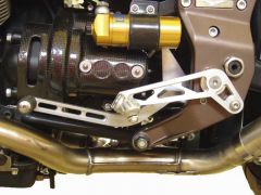
Hi Brian, I've sent you a PM. I have loads of the Schnorr M6 washers on hand. I supply them on my foot forward comfort controls and buy them in bulk. John
-
V11 Ballabio, Cafe, Coppa--How to Disconnect Lines Underneath Tank
Ryland3210 replied to tmcafe's topic in Technical Topics
There is only one right way to install the tipover valve to have it work the way it's supposed to, and not allow a vacuum to be generated in the tank and fuel is consumed. Check this in the FAQ section for details. You'll find a link to diagrams towards the bottom. http://www.v11lemans.com/forums/index.php?showtopic=462 -
A very well designed three piece set of plastic covers to protect the rear suspension and other components is available from "edge", a forum member. These have been installed by many members with good results. There are two versions: one for those who wish to keep the "hugger" fender, and those who wish to eliminate it. http://www.v11lemans.com/forums/index.php?...ost&p=67956
-
Ryland post on measurements "Filter Cover Tool" September 18, 2006: "I've taken the time to make careful measurements, and here is what I found on my '04 Cafe Sport: Dipstick calibration results: My dipstick length from the flange to the tip is 7-9/16". With a filter change, thorough draining of the sump, then adding 3.5 liters per the manual and running the engine long enough to fill the filter, the oil level reached 2.09" from the end of the dipstick with it fully screwed in, or 5.475 from the flange . That's 0.69 higher than its full mark, but still 0.33 lower than the gasket along the dipstick, or 0.23" vertically. This corresponds with the full mark being 18.23mm from the block surface, and when the wetting of the oil during extraction of the dipstick which causes an artificially high reading is taken into account, this agrees almost exactly with Ratchethack's visual measurement of 21 mm. This suggests that the dipstick calibration as supplied with the machine is incorrect. In another post, I recall it said the correct method is to measure with the dipstick not threaded in, opposite to the manual's instructions. That's about 0.5 inches higher, but still significantly lower than the 0.69 I measured. However, it's difficult to ensure the dipstick is parallel with the thread to get the right reading. I prefer the screwed in method, and plan to put two new marks on the dipstick: One for when the bike is perpendicular, and another when it is on the sidestand. With a difference of 0.69 from the dipstick full mark to the measured oil level, I have to assume a flashing oil warning light could well indicate oil starvation under acceleration, especially if the oil level is near the lower mark, and since the pickup is towards the front of the motor. Unless someone comes up with a theory to discount this, I plan to proceed on the assumption the 3.5 liter specification is correct. As of November 13, 2007 The picture below shows the dipstick fully screwed in with Roper plate installed. Distances from the Roper plate are 1.12 to the full mark, 2.63 to the tip. With a change of filter and refill of four quarts, the actual level came to 0.88 below the plate along the dipstick, equivalent to 0.62 inches vertically. " I have cut a notch in the dipstick at 0.69 inches above the original full mark for my personal 3.5 liter full mark. When changing oil and filter, I used a total of 4 US quarts (3.7854 liters, 3.33 Imperial Quarts) before installing a Roper Plate, which is slightly above the 3.5 liter mark. With a Roper plate , I have increased the refill to 4.5 US quarts, which is still safely below the plate to avoid windage. FAQ Administrative Contact: ---------------------------------- Please feel free to contact this FAQ's administrator via Forum Private Message to submit new information or suggest corrections. Ryland3210
-
It's a good suggestion. For things like that I have to pay for a guru/geek, because I've never been interested in website construction. I think setting up a credit card acceptance system is easier, or so I've heard. How would you feel about that? Of course money orders are OK as well as checks. regards, John
-
Gosh, I seem to be giving away the store at $8! My cost has just gone up by $.52. I may have to increase prices, unless I can buy in greater quantities.
-
The manual's procedure ends with checking the TPS with throttle closed. If it is incorrect, one has to correct that, and start all over. The forum's procedure is designed to make progress step by step to avoid trial and error adjustment. Accurate voltage (degrees) measurements depend on the 150 mv basis. There is no advantage to going through the procedure, and then checking the 150 mv. That's a classic case of putting the cart before the horse. To measure the 150 mv baseline, the right throttle plate must be fully closed. To ensure that is the case, the safe bet is to disconnect the connecting rod, back out the right idle screw, AND make sure the "choke" allows the throttle plate to fully close. I believe that by "fully home" in the manual's procedure means out (this terminology also used on some machine tools). This puts the right idle screw in control. The problem with that is that the connecting rod linkage switches from compression to tension when coming off idle, so if there is any backlash, the synchronization between the two throttles will vary. The forum's procedure puts the left idle screw in control with the right backed out. That keeps the connecting rod in tension always, so backlash does not interfere with synchronization. Stick with the forum's procedure is my advice. It's the result of detailed analysis and the contribution of several experienced Guzzisti's. There is the minimum of trial and error. Since the left idle screw is in control, you can also easily adjust idle speed in the future by simply adjusting that, without fear of upsetting synchronization.
-
-
-

