docc
-
Posts
19,906 -
Joined
-
Last visited
-
Days Won
1,130
Content Type
Profiles
Forums
Events
Gallery
Community Map
Everything posted by docc
-
I'm not sure I understand the value of investigating the original relay as it was proved failure prone from mid-2000 year. Yet, my 2000 Sport was delivered with the same relay in all four 4-pin (SPST) positions, and a different 5-pin (SPDT) in position #1. As mentioned, my dealer sent me a larger Siemens for the Start/#1 position very shortly. Original: Siemens V23073, the 4-pin are -B1005-A302 and the 5-pin is -B1008-A303 I see no markings indicating surge protection (either "R" or "D"). Certainly the #5 position relay was not different from the other SPST positions. Only the SPDT in position #1 differs. I cannot find data sheets for these old relays.
-
"... V11 before 2003 (likely including the 2003 "Carryover Sport") do not have a hardened fastener at this pivot..." No. I am basing that on it having been stated the part number changed in 2003 and the fact that my early bolt has no headstamp and the replacement does (10.9). Along with the fact the original bolt configuration is NLA from Moto Guzzi (superseded?). AFAIK, there is no torque specification for this fastener in the Guzzi chassis. It is fastened with a lock nut ("NyLoc" type). Whether or not the bushing is intended to be "clamped" has been the subject of debate. I question whether this fastener could suffer from being unnecessarily overtorqued, leading to failure (especially the earlier, unrated, fastener). Also, whether the two fastener failures we have in question are actually best described as "shear" failures. Technically speaking, probably not. This is why I am asking both @LowRyter and @kalev11 to clarify the more exact description of their failures. Both of these examples are 2001 models. Finally, @LowRyter, to clarify: I have no failure, only replacing pre-emptively with what appears (to me) to be a superseded part. Learning from other's experience. Thanks for posting this!
-
I am off the phone with Curtis at Harpermoto in the US (Missouri). He states the the later (hardened) bolt is available in NA and will make an order this afternoon. He confirmed the size is M10 x 1.5 x 59. I have committed to six of them (to replace mine and share), and he will have four left on hand. $2.60US each + S/H. He suggested putting together a kit which includes the lock nut (good idea to fit a fresh one) and the washer and spacer (most expensive part at $4.75US). I suggested we leave it at just the bolt and let folks decide what else to replace. For example, his careful discussion led me to see that I have no "washer" and my "spacer" is on the bolt head side. [edit: this configuration is shown in the Parts Catalog for the "2nd Series" V11 Sport 1999-2001 with the 1.5 thread pitch bolt.] Time to delivery is a hopeful 2+ weeks . . . (certainly in time for the sSSR in Kentucky). A couple take-away from this important thread, so far: Do not neglect cleaning and greasing this critical pivot. And, perhaps the greater discovery: V11 before 2003 (likely including the 2003 "Carryover Sport") do not have a hardened fastener at this pivot and an upgrade to GU01357731 may be worth considering. https://www.harpermoto.com/screw-10mmx59mm-01357731.html
-
Where are these bolts shearing @LowRyter, @kalev11 ? At the head or at the thread/shaft interface?
-
When the new Picker Components relays arrive (in a few days from onlinecomponents), I am planning a V11 RelayFest /TechSession. I can tell you the original Seimens are small, and the very first warranty/dealer support I received was a larger Seimens to fix in the Starter Relay/#1 position, as the troubles were already being reported. I'll report back with dimensions, yet we certainly found weight is an indicator: " . . . [OMRON G8HE] 20.0 grams with my analog method. For comparison, my original Seimans are 15.1 grams."
-
My early bolt has a smooth head, no markings, indicating mild steel/unhardened. Do the later bolt heads (2003-onward) reveal a hardening level (i.e.: 10.9 or 12.9)? Knowing of these failures, it seems prudent to go with a hardened fastener in this location (as well as seeing to the maintenance). I wonder if Moto Guzzi superseded the part thusly . . .
-
My original relays are in the their prescribed location: shelved in the pile cabinet, properly labeled , one example of seven generations of relays I have run on mySport (I skipped the TYCO, not haven fallen for that).
-
According to this French site posted by @p6x, the part looks available, but the part number is different than from my 1999-2001 catalog (GU37357706): https://www.pieces-motoguzzi.com/guzzi-laverda-scarabeo/affectation_pieces_detachees/GU01357731 While MGCycle doesn't bring this number up (nor the number I posted), Harpermoto does show the -7731 part at $1.20US. This does NOT mean they have it! A call to Curtis is the only way to know: https://www.harpermoto.com/screw-10mmx59mm-01357731.html @LowRyter and @kalev11, where did your bolts break: at the head or at the base of the threads?
-
I can get close with Mcmaster-Carr, but the minimum thread length looks like "26mm" and our application appears to be less than 20 of threads. So, the linked 60mm would not have enough clear shaft area. Perhaps buying the bolt longer and trimming it to length leaving the correct amount of the bolt shaft unthreaded . . .
-
Parts Catalog for GU37357706 ("1st Series") states M10 x 59 (mm long), yet sourcing one with that much shaft area may not be as simple as a stop by the hardware store . . .
-
That is good thinking and very possible. I have seen others dismount the relays for clearance. Also, I have sen the bottom of the seat pan "relieved" with a rotary tool (i.e.: Dremel®), and even seen the entire pan material cut away above the relays exposing only the foam material. It is evident when inspecting under the seat when there is seat pan contact with the relays. There are very distinct signs of abrasion and "dusting", dulling, or chafing where there has been contact. Good method to observe the corners and edges of your relays for this and take action to create clearance. (Added to the Underseat Maintenance Checklist )
-
Talking about the frame end? Definitely an issue. When was the last time any of us inspected that? A formula for disaster when neglected. Kudos to your technician finding that. It should be inspected, cleaned, and greased with waterproof grease at every rear tire change . . . https://www.v11lemans.com/forums/topic/22039-torque-reaction-rods/ The torque reaction rod bushings , and its pivots, are a line item in the Wheels Off Maintenance Checklist:
- 98 replies
-
- 11
-

-

-
See? Corvettes are meant for sliding sideways. Volvo and V11? Not so much . . .
-
Even with a heated jacket, this is my chosen limit (5ºC/40ºF). Not because I can't get comfortable, but more that I don't think the tires get the memo to also relax and get to work. After two of my (expert riding) buddies had traction loss crashes in near-freezing temps, I realized my Swedish car would light an ice warning at 38ºF/~3ºC. I figured the Swedes know quite a lot more about ice on the roads than I do and adopted the new limit for riding safety.
-
That makes perfect sense, and explains why @Speedfrog sees that vulnerability from Relay#5's coil powered by the same feed as the ECU "downstream" from Relay #4. So some questions, do this spikes only occur when the coil is powered on and off, or do they occur continually? Also, is the magnitude of the spike amplified by the size of the coil? Always thinking "bigger is better," the OMRON G8HE have 1.8 watt coils, the CIT and PC that are refeneced are 1.5W (the CIT I am using are 1.2W). Perhaps the smallest effective coil is better as long as there is no "bounce" (Loss of contact from vibration or impact)? Finally, do the resistors serve some of this function by "buffering" the spikes? Enough to be adequately effective?
-
I admit I do not understand from where the voltage spike would be coming from and across what terminals of the relay the diode would block it.
-
Yes indeed, @Speedfrog, you are absolutely correct in this. I stand corrected having remembered this wrongly and having failed to look at my references before posting. Welldone, sir, and thank you for your diligence! About those beers I owe ya . . .
-
I would venture that Relay#5 is "pulled in" or turned on by the Ignition Switch/Run Switch through Fuse#2 (no "sensitive electronics"); Relay #5 then "pulls in"/ turns on Relay #4 that puts power to the ECU; The ECU then triggers/controls the coils and injectors directly without going through any of the relay system. Check my work . . . edit - @Speedfrog has this corrected in the very next post.
-
Ah, it seems DigiKey is 1/3 the cost, depending on shipping and tariffs. I also recall that DigiKey has a European distribution center. I have added the DigiKey link to the "Answered" post as an update along with the datasheet linking directly to Picker Components. I see that Relay#5 supplies power to pull in the ECU (#4) Relay, but can we say it is "controlled by" the ECU? I seems if we seek to protect "sensitive electronics" we would want a diode in Relay #4 to protect the ECU (?)
-
I have ordered four of the Picker Components relays from onlinecomponents. $10US each with the shipping and taxes(tariffs). I'll sacrifice one to compare construction to the OMRON G8HE and the CIT. I am especially interested in the bulk of heat sink and the mounting /location of the resistor. One of these will go into Position #1 of my early Sport. This uses the weaker N.C. contact in this "load shedding" start relay to carry all of the load to Relay#2 from a 15 amp fuse. One of the reasons a relay rated 10 amps/ NC is not ideal for this location. The Picker relay has the highest rated NC contacts I have seen at 25 amps. Good find, @Speedfrog!
-

Hare-Racing-PCIII-Dyno-Tune-PCIII-June-20-2003.jpg
docc commented on al_roethlisberger's gallery image in Members Gallery
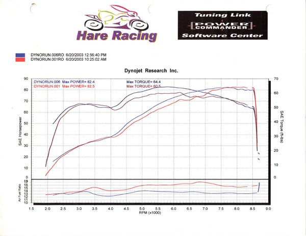 What a difference 2 1/2 hours of DynoTuning can make. Of course, there may have been a lunch break in there . . .
 -
Three minute warm up? Sounds painful. Not enough charge, not enough oil moving in a cold motor. Start up, swing on, ride off. Keep the R's under 5k for maybe 10 kays, then let'r rip! "Trickle chargers" can be damaging to the Odyssey PC545 if their float voltage is below 13.2v (according to the manufacturer). The handiest charger I have for the V11 is a 6 amp manual automotive charger. When the static voltage drops to 12.65v, turn the lights on for a few minutes, then hook up the charger and bring the voltage to 15.0 monitoring a voltmeter. If the battery has been more deeply discharged, repeat this procedure up to several times.
-
If the Yardbirds doesn't date us, J.C. Whitney certainly does!
-
Looking forward to seeing what you find, @audiomick! Thanks for the extra effort. Beyond simply sourcing proper relays, this thread started as, and has remained, a tutorial for those looking to learn and understand the various factors and terminology. Even I can read a data sheet now! Combining some of things we have learned from informed experts, it occurred to me that there is a place for the sealed relay case on the V11. Not for moisture, necessarily, but in the event silicone "dielectric" grease is used on the relay base contacts. There are good resources that state the vapors are oxidized by nearby switch contacts (like relays) creating silicone dioxide (think of plating your relay contacts with thin layers of glass). Glass is an extraordinarily good insulator, but electrical contacts thrive on conductivity Based upon this premise, those who use silicon based dielectric grease on their relay bases should consider sealed relays. Or simply switch to a petroleum based grease, like @Kiwi_Roy's favorite: Vaseline®, or @Chuck's favorite, Caig DeOxit® (I prefer the "Gold "). The concept @audiomick now presents, that relays are "Verschleissteile" ("wear parts") suggests that they should have a service/replacement interval without waiting for them to fail (always occurs at a bad time).
-
"Answered" post edited, once again, to keep current sources on High Current relays for V11 applications.