-
Posts
550 -
Joined
-
Last visited
-
Days Won
8
Content Type
Profiles
Forums
Events
Gallery
Community Map
Everything posted by Gio
-
Thanks Ken - I did do a search before asking (maybe forgot to do the refresh for relevance thing) ... from your old thread I like the idea of a repair kit as am guessing the entire OEM cable would be $$$ Roy - can you provide specific info on part # and (Canadian) source of the one you found ..? Cheers, Gio
-
Speedo quit a couple of days ago and so was expecting problems with either the guage or one of the angle drives - but the inner cable drive broke about 3 inches down from the guage end ... not bad considering how many turns it must have done in the last 13 years. Does anyone know the part # or equivalent replacement options for the inner cable? Gio
-
I put a HyperPro (part # DS-075RA - 75mm stroke - NOT the one they listed for 97+ V-10/V-11 Sport which was wrong) on my 2000 Sport in 2007 and have been very happy with it ever since. The Bitubo is a piece of crap and leaked almost from day one. Gio PS - Love the green wheels ...
-
See post on my experience with the Z8 rear / Z6 front : http://www.v11lemans.com/forums/index.php?showtopic=17471&page=2 I was dissappointed with wear on the Z8 rear (squared off badly), but handling wise it was ok. I plan to switch back to Pirelli at next change. I see no reason why you shouldn't run a Z8 front with your Z6 rear ... hopefully the Z8 would be quieter than I (and others) found the Z6 to be .!
-
LowRyter - I also had no luck in sourcing a 170/60 Angel GT ... seems they are not generally available as yet, but plan to go this way at next change. Gio
-
Hi Docc, I was thinking more in terms of the front discs, but on closer inspection the "buttons" on the rear are indeed just direct bolts to the wheel so have that covered with just regular caliper service. When you applied this CLP stuff (and assuming negligable throw off onto the braking surface) ... did it affect the performance of the front brakes ..?
-
Actually no - am quite familiar with caliper / piston maintenance (but thanks for the reminders!) ... I was referring to what I call the "buttons" that attach the brake disc to the carrier ie the things that make the discs "float" - my understanding is that it is these that allow the discs movement as required, but have never really given any thought as to any maintenance that may be required to keep them "floating" ..?
-
Just replaced my rear tire and so was doing the usual obvious things whilst wheel was off (shaft lube, bearing check, pad check / caliper service etc) and got to wondering about the buttons that attach the disc to the carrier ... not so much for the back but am planning on checking the front brakes next. This is something that I must confess to have not paid much attention to in the past ... I did some searching and came across some cautionary discussion of penetrating oil, appropriate lube (dry) and also docc's mention of using a mallet to ensure the buttons are free and the disc centred on the carrier in his checklist. Just how much discernible play should there be in the buttons I wonder? In the case of the rear, I could not detect any. I would be more concerned about the front than the rear ... healthy front brakes are a good thing! Thoughts /advice anyone?
-
It's been a while since I fitted mine, but as I recall the kit clip-ons are indeed a little lower than stock. The other modification I had to do was to re-shape the front brake reservoir bracket slightly (just a little bend / twist) to improve clearance ... Gio
-
No worries Carl - and I'm sure I speak for many others ... your schematics are a great resource!
-
Interesting. Regarding the wire break below the ignition switch (actually upon removal it was found to be about half-broken) - correct, there was bending in the loom to the AMP connector at that point - the sleeve had already cracked and the wire was next in line. I guess these wires are going on 14 years old now and have become quite accustomed to their shape!. When I removed the lower (electrical) part of the ignition switch - I found that there was nothing gripping the loom as it exited the hole in the base - so with flexing each time the bars are turned this must be what caused the internal connection to break. This is why I wrapped the first few inches with the self-adhesive tape (to cover the repaired region) and added some support - there is a natural bend to the left as the looms heads towards the AMP connector and it passes very close to the speedo cable drive - the support helps clearance there also. I also made sure the routing to the AMP is as free as space permits. Now - time to fit the new rear tire and some upcoming riding weather! Cheers! Gio
-
Hi Roy ... thanks for clarification - I guess I was thinking di-electric grease might be better where electrical conductivity is required (?), but will defer to your greater knowledge/experience. Now if only we could source cherry flavour for the docc ...
-
-
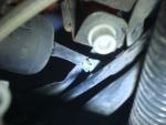
Hi Docc That combo makes sense - vaseline for the mechanical and dielectric for the electrical ... I just solved the problem. Having removed the lower section of the electrical part of the ignition switch (3 plastic retaining tangs), the F6/7 switched wire was seen to be detached - so re-soldered it back in place and now both circuits switch ok. There is nothing really supporting the short loom that goes from the ignition switch to the AMP connector and so I bound everything up using that stretchy self-adhesive "emergency" tape and added some zip ties to alleviate strain (see attached pic). All good. Gio PS - Apparently the cherry stuff works really well - I'm told the Harley guys use it on their tools to prevent corrosion or something ...
-
To add further clarification - when you guys suggest vaseline - is this with respect to the mechanical side of the switch or the electrical side, or both ..? In my case, the mechanical side of the switch seems ok so am not planning on removing those security bolts, just the two cross heads that liberate the electrical side ...
-
Thanks Roy - I'll try as suggested. As a back-up plan - I like your idea of combining the two switched circuits into one. My only concern would be then that the current for headlight plus taillight/indicators would be going through the same wires (at least for some distance - eg if combining was done at or just before the AMP connector) ... ie that this might over-load the already questionable routing of headlight supply via the IGN switch - perhaps this is the universe's way of telling me that I should do the headlight relay modification ..? I'll open up the switch and report my findings - hopefully the wipe-out and vaseline refresh will get that second circuit to switch. Gio
-
Update Still chasing this problem. Removed the ignition switch (via removal of the top triple clamp and two bolts through the dash) but discovered that - with respect to the AMP connector, there are differences between the 1999 schematic referenced above, and the actual wiring on my bike. Schematic shows ignition switches I+J (pins 1+2) for the headlight (which works) and K+L (pins 3 and 4) for the missing F6/7 (indicators / taillight) - but in fact I+K (pins 1+3) switch the headlight and J+L (pins 2+4) the missing items. I confirmed this by jumping pins 2 and 4 on the AMP connector and saw the indicators working. (Jumping pins 1+3 activates headlight also) I repaired the damaged yellow wire (L or pin 4) but still only get switching between pins 1+3, but not 2 and 4 So my problem would apear to be in the switch (or associated wiring tail). The black (plastic) part is held on by two cross-head screws, can be removed and (presumably) contains the moving electrical connectors. The upper (metal) mechanical part of the switch seems to be working normally (as evidenced by working headlight) ... Question - how to I take apart the electrical portion to determine where the problem might be?
-
Thanks Chuck ... I suspected that was the correct answer!
-
Thanks for the tip Roy ... I think I'm going to try and repair in situ (?) but if not enough room and the switch needs to come out (and probably will) - will take your advice re some fresh lube. I have some di-electric grease and am aware that this can cause un-desireable conduction if used too liberally - so is regular petroleum jelly a better way to go for such an application?
-
Removed the tank and followed the cable back - indeed the 4-way was not too far back (~12 inches or so of cable) and I think there should be enough slack to allow better movement if re-routed slightly (it's a bit cramped in that area in my case as I run fuel lines to the filter which is housed behind the Magni fairing - part of my solution from the bad old vapour lock days - fuel pump now mounted on top of the spine) ... wishing the break was just a little further back from the Ignition switch in which case I might be able to repair in situ, but that's how it goes sometimes eh? Cheers Gio
-
Carl - just wish to add my thanks for providing these diagrams ... Gio
-
I think I have found the problem. There is 12v @ F4 which then goes via the Ignition switch to feed F6/7 when switched - so I speculated a break somewhere between the other side of F4 and supply side of F6/7. Upon inspection there appears to be broken sleeve on the bundle of wires about an inch or so below the IGN switch and what looks like a broken wire inside (yellow/green?). See pic. This is in a tricky place to access - will need to remove the tank, and possibly the IGN switch in order to verify / repair. I think I read in another post of problems in this area - according to Carls diag there is a 4-way amp connector (#38 on his diag) which must be under the tank somewhere - perhaps there is insufficient length / bad routing between this connector and the IGN switch and the cable is then stressed as the bars are turned ..? Gio PS - How easy is it to remove the IGN switch ..?
-
I checked Roys test point schematic and both F6 (lights) and F& (indicators) seem to get their feed from the Ignition switch ... but no harm in swapping the relays around to see ... I'm pretty sure I have everything else ..?
-
So I think the same mice that sanded down my rear tire over the winter, may have been helping themselves to the wiring buffet ... Bike starts, and I have everything except indicators, tail light and licence plate light. So with reference to Mr Carl's wiring diag (19 Nov 2010 version of the 1999 wiring) I have checked F6 and F7 - both are good, but with Ignition on (and fuses out) there is zero volts on the supply side (and ~ 0.2 v on the other) ... so am now trying to trace back and find the missing electrons. If this rings anyone a bell, or if you have suggestions it would be much appreciated. Gio
-
Not exactly sure what you mean by side pan bolts - but would suggest that you spread the weight across the entire sump if possible - I use a hydraulic car jack with a large block of (soft) wood for this purpose ... Gio


