-
Posts
2,345 -
Joined
-
Last visited
-
Days Won
61
Content Type
Profiles
Forums
Events
Gallery
Community Map
Everything posted by Kiwi_Roy
-
That is odd, I always thought there was a standard gear ratio for the inside of a speedo. If the km reads correct it should be spot on, they didn't change out the face did they? I have plans to remove the bevel gearboxes on mine at first sign of quitting, I have a longer cable someone gave me. I have to remove the gearbox at both ends otherwise it will run backwards.
-
All we need now is for the original poster to report back
-
David, if you take a quick survey of Carl's drawings tracing the wiring from terminal 30 of the start relay the 1999 Vll Sport does, and I know my 2001 does http://www.thisoldtractor.com/guzzi007/sportissimo.html But almost all the other bikes before and since feed the start relay via the ignition switch. If you measure the current drawn by the solenoid with a multimeter it shows less than 10 Amps which shouldn't be a problem but this is just the holding current, the real work the solenoid does is in the fraction of a second between the time the start relay closes and when the solenoid closes it's main contact, it takes a massive magnetic field to engage the starter gear A Valeo will pull about 50 Amps, a Bosch about 40 If you calculate the resistance of the two coils in parallel it works out ~ 0.2 Ohms Say for argument sake you had a total resistance of 0.2 Ohms through all the wiring, ignition switch, fuse, relay the instant current would be 12 / (0.2 + 0.2) = 30 Amps By cutting out half the wiring it's reasonable to think you could at least cut the resistance in half e.g. 0.1 So now the current to pull in the starter is 12 / (0.1 + 0.2) = 40 Amps BTW I think I am being realy generious in saying the total wiring is only 0.2 Ohms, I have seen the ignition switch alone many times that. I honestly don't think Guzzi understand there are two coils in the starter solenoid otherwise they might show it in their schematics. A usefull calculator http://www.sengpielaudio.com/calculator-ohm.htm Using the calculator 30 Amps 0.2 Ohms = 180 Watts - This is the power available for the solenoid to do it's work, the power dissipated in the wiring is lost. With a better circuit 40 Amps 0.2 Ohms = 320 Watts - Almost double the power Roy
-
Slightly off topic rant That's a rip off IMHO Belfastguzzi hit the nail on the head though Have you seen one schematic that shows how the solenoid is really wired? On my 2001 VII Sport they finally got the wiring right then they reverted back to running the wiring through ignition switch. Most bikes can be improved with just a simple wiring change. It should go Battery, Fuse, Start relay (30), Start relay (87), Start solenoid any time you see the start relay fed from the ignition switch it's just plain STUPID Valeo Starter.pdf Reading the original post again you say the rev counter is not working, that means the headlight relay is not picking up and BTW the bike will not be charging. Guzzi Wiring - Simple.pdf So my guess is fuse 5 is blown, If it looks ok pull the start relay and measure for Voltage between pin 30 of the socket and chassis, you should have 12 V there. Some bikes are wired slightly different but either way the normally closed contact of the start relay powers either the coil or the 30 terminal of the headlight relay, The 87 contact of the headlight relay powers the tacho, Voltage regulator and the headlight Hi/Lo switch PM sent Roy
-
I have a different interpretation of the symptoms, I'm not saying it's the correct one. Headlight relay dropped out for some reason, a blown fuse perhaps This immediately takes out the tacho and since the regulator is fed from the same point the bike stops charging (in daylight you wouldn't notice the headlights off) The charge lamp won't turn on because the regulator without 12V cannot turn it on After a while there is not enough Voltage to run the flashers or it's also possible they are fed from the same fuse that took out the headlight relay A short while later the battery is completely flat and the engine dies. So I would start looking for why the headlight relay dropped out. Perhaps start by seeing if the flashers work with a charged battery. Check the regulator is getting 12 Volts on the black wire (black/white pair) to chassis with key on. BTW, there's no connection between the fault you had two years back and this one. Roy
-
I think Docc is right As for the Tacho it's fed from the headlight relay, check if the headlights on If not check to see if the start relay is a 5 pin variety Guzzi_Wiring July 21 2010.pdf The starter not working could also be the fuse feeding starter relay (Fuse 5 on mine), the relay would still click, this would also account for the tacho. Note: Most bikes are wired a little different around the start and headlight relays.
-
I don't know, but it seems Docc was right on the money if you read GScott's last post.
-
I cut mine apart and extended it up the front of the tank, just ty-wrapped to the frame.
-
All the little diode is doing is compensating for the Voltage lost when the previous owner added headlight relays. If you have a stock bike (without relays) with the key and headlight on if you measure from the battery positive to the black wire at the regulator you will find about 1/2 Volt. This is compensated for by the regulator being set at 13.8 Volts, the battery will charge to over 14 (engine running) When you add after market headlight relays powered directly from the battery you loose the benefit of this 1/2 Volt drop so the battery only gets charged to 13.8. The diode adds 0.6 Volts by making the regulator think the battery is 0.6 Volts lower. I will add a sketch later
-
Actually it was me that told Ken to add a diode, it causes the regulator to boost the Voltage by 0.6 Volts at higher revs. With the stock wiring there's a natural Voltage drop of over 0.5 Volt between battery and regulator reference (black wire) but when you add headlight relays powered directly from the battery this Volt drop is reduced to zero so the battery gets under charged. You can easily verify this voltage drop, just turn the key on and measure between battery positive and the regulator black wire of the black/white pair (stock wired bike of course) At low revs the Alternator output is less than the load so the regulator isn't regulating at all, just sending the total output of the alternator to the battery. But if the battery is charged to a higher Voltage at speed it will take longer to come down at idle. This only applies to the bikes with Ducati Energia regulators.
-
Thanks for the help, Roy! The battery is connected properly. I will test the alternator. With the bike completely off, the red wire holds the same current as the battery. Is this how it should be? I don't understand, the Voltage at the red wire will be the same but there should not be any current at all, Inside the regulator are a pair of diodes pointing towards the battery (current flow is from regulator to the battery with the engine running) You said earlier that the fuse only pops when the red wire is connected, I took this to mean when you plug the pair of red wires from the regulator into the single wire of the main loom. With the bike off there should be zero current flowing in the red wire with or without the regulator connected to it. A couple of times lately I interacted with owners who had a short circuit that causes the small black ground wire from the ECU to chassis up under the tank burn up. In doing so it can melt through adjacent wires thus shorting them to ground. When disconnecting the battery it's very important to get in the habit of removing the Negative cable first and reconnecting it last. Do this and the chance of a meltdown are greatly reduced.
-
Youre probably right, If you get a new electric one ty-wrap the wires to the body that way they won't pull out so easy. You might be able to re-attach the wires but $45 might prove cheaper.
-
Your diode reading is about right 476 milliVolts, that's the forward bias Voltage. The #1 in reverse should be the same as without the leads connected (open circuit), different meters indicate this in different ways like "---" With the original wiring the Voltage drop between the battery and the regulator reference point is about 0.6 Volts, When headlight relays are powered directly from the battery you loose the benefit of the Voltage drop and so the battery gets under-charged Adding a small diode in series with the black wire boosts the regulator output by about 0.6 Volts (any small silicon diode e.g. 1 amp will do) Before you do that though, have you added a ground strap from the regulator case to engine, that often cures low regulation. You will find a small black wire under one of the holding bolts, it's too small just add another short #12 from the other bolt to the engine. Roy Charging Circuit Problems.pdf Sorry, I need to revise note 2 mentioning the normal voltage drop. Most bikes don't pass the headlight current through the start relay, just the headlight relay. On my 2001 V11 Sport it passes through both as I show.
-
Every one else seems happy to get over 30 to the gallon, Cliff gets 47 I have one of his MyECUs and get about 30, I have been too lazy to dial it in. I hope to have an O2 sensor shortly, even another 10 MPG and it will pay for itself in next to no-time. Roy
-
I found the same thing, TPS would not always go to the same place or Idle at the same speed. I put this down to slop in the linkage So in spite of what others say I used the right throttle stop as well, now it always goes to the same mV and idles more consistent.
-
That's a good idea, it's not so easy to probe the wires with a pin. 68C is referring to the wires that go to pin 22 and pin 11 of the ECU connector Do you have your MyECU running yet? BTW if you need to probe the ECU socket the pins are the same size as used in the earlier computer cables you can purchase them at Radio shack or simply tear apart an old computer cable
-
Then I'm afraid to say the regulator must be toast, the red wire is connected internally to two diodes, there should be no current flowing back in. Look at the simple schematic I posted earlier. I would also inspect the alternator where the wires connect and test for a short, it seems strange to me that the current would flow back through a diode and an SCR. A stupid question - you don't have the battery connected backwards somehow? Roy
-
The first thing I recommend with charging problems is to add a good solid ground strap between the regulator and a timing cover bolt. Grounding is very important as the pulses of current flowing exceed 30 Amps. While you can afford to loose Voltage in the positive wire from the regulator to the battery any Voltage lost between the regulator case and the battery negative is subtracted from the battery voltage, Loose half a Volt and the battery will be half a Volt lower. Charging Circuit Problems.pdf I assume you mean the 30 Amp charging fuse, it should never blow without the bike running, unless perhaps you have a short. Unplug the red wire at the regulator and put in another fuse, if it blows there is probably a pinched wire in the loom somewhere. It's also possible someone accidently grounded the battery positive terminal to the ECU case, that causes the ground wire in the loom to become red hot and melt it's way through the insulation of other wires grounding them The red wire goes from regulator to fuse to battery. Reconnect the red wire at the regulator, if the fuse blows it may be a bad regulator but I doubt it. Roy
-
Roy, what are your experiencies? Do you like the new tensioner? Everything as smooth as before? Hubert I can't say I notice much difference, the new tensioner certainly looks like it's going to do a better job. I know I will never have to do the chain again, and the oil pump gears look fine. The bike runs really well but has an annoying habit of skipping a spark every few seconds at idle, I proved this with a timing light. I thought it may have been timing chain slop, so that's one more thing eliminated.
-

V11 Le Mans Leaks Oil, Relays Arc, Bought It Anyway
Kiwi_Roy replied to Bob Hartman's topic in Technical Topics
Bob, Did you ever figure out the snapping noise? -
I agree with this, every time I use the kill switch I wonder why the bike won't start There are a few other things that it could be as well, I sent you a PM
-
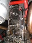
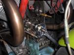
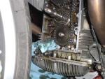
All back together. No - I didn't jamb a brass drift in the chain to tighten the nuts, I did to remove them because I was replacing the chain anyway. To tighten I put the bike in top gear and foot on the brake. I can't believe how crude the OEM tensioner is compared to the one from MG Cycle. Hopefully it will cure the sneeze Because the original bolts are too long to simply screw back in without the bracket I hacked it off and scratched on a message for the next caretaker Many thanks to Carl for pointing to the upgrade and Jaap for the picture of one installed Roy
-

V11 Le Mans Leaks Oil, Relays Arc, Bought It Anyway
Kiwi_Roy replied to Bob Hartman's topic in Technical Topics
Hi Bob, Sounds like you got a nice bike there, barely run in for one of these motors. I have no idea what the snapping sound could be, if it's quite repeatable perhaps some sort of short circuit in the flasher circuit, the flasher bi-metal would get super hot and open then take a while to cool, I'm only guessing though. Pull the flasher relay then each fuse one by one until it stops. The closest drawing Carl has shows the flasher is powered through the ignition switch but the PO may have done some re-wiring. Could that be the reason he had it on charge? -
Thanks Jaap, I was worried perhaps the tensioner was intended for a different engine. On first sight the original looked OK but I was able to push it to the case and it would sometimes stay there. All I have to do now is figure out how to get the nut off the crankshaft Update, A 3/4" drive 32mm socket fits over the shaft. I ground a couple of flats on it and spun it off with a 12" Crescent wrench. Wrap a couple of turns of masking tape over the shaft to protect it. What was I doing wrong there?
-
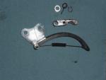
I decided to change the timing chain and tensioner, I purchased one from MG Cycle When I pulled the old one out it's hard to see how the new one will fit in its place. Can anyone please confirm if is right or wrong. Thanks Roy Old one at the top New one at the bottom


