-
Posts
2,345 -
Joined
-
Last visited
-
Days Won
61
Everything posted by Kiwi_Roy
-
I have re-read the post trying to get a good feel for the solution. Some additional Info Charging Circuit Problems.pdf Charging Circuit Problems2.pdf In summary. If the regulator is working OK you should see about 13.8 Volts between the black reference wire and the regulator case with the engine running. If the battery is over-charging suspect a Voltage drop between the battery and black reference wire. If the battery is under-charging suspect a bad ground on the regulator. The ground wire provided is totally inadequate for the high current that flows. The 30 Amp fuse can also have a bad contact resulting in it heating up and/or melting with under-charging. Of course it can always be a bad regulator The V11 Sport has one of Guzzis beter wiring schemes, the reference doesn't go through the ignition switch as on some other Guzzis. Motto Guzzi - making electricians out of riders for 90 years.
-
First thing to do is remove the battery connections, scrape the terminals then add Vaseline, the terminals sometimes oxidize disconnecting the leads even though the bolts are tight, Vaseline will prevent this. Next trace the main ground lead from the battery to the chassis, make sure that's clean and tight. Check if you have 12 Volts on any of the fuses to chassis and report back which fuses are live with key On / key Off. Besides the other good suggestions My friend has a LeMans about the same era, he found one of the wires had broken off where it was soldered to the ignition switch, if wires are allowed to flex at a soldered joint they will soon break, if that's the case please post a photo. If the bikes been parked for a long time it's possibly just the grease in the switch has gone hard with age but that would usually show up as an intermittent fault, if you pull the switch off at all it's a good idea to clean it out and replace with fresh Vaseline. Did it just happen suddenly or has it played up for a while? Ritratto98 point's out a common fault, there's a couple of connectors under the tank LH side where the switch connects to the loom, they sometimes work loose Good Luck Roy
-
The shakeproof (star washers) was a good way to make a good connection (for grounds), then a few years ago, General Motors (I was a GM tech for 30+ years) came out with a bulletin stating NOT to use the star washers and just to have a good clean surface. My guess is that moisture will creep into the connection and oxidation will occur causing a poor connection over time. So, I take their advice as they know and see alot more than I. Just a thought, Mike I'm a great believer in the power of Vaseline on electrical joints, it excludes air and moisture thus preventing corrosion, at least that's been my experience over 50+. Actually any greasy substance will do the same but vaseline is not so messy, cheap and available everywhere. Steel and Aluminium in a wet salty environment like the V11 regulator location, is that good?
-
+1 on that, Kev has picked out one that looks really good, it eliminates several weak wiring points. I have spent a lot of time with the Ducati Energia, I think it's a good unit just badly applied although the V11 Sport has one of the better Guzzi wiring schemes. If your charging is weak add a decent ground strap, on the V11 the regulator is bolted to the horn bracket which is bolted to the bike, neither of the connections are electricaly sound and the small black ground wire Luigi provided is totally inadequate, the current through the ground peaks at over 30 Amps. I ran a short wire (about 6") from a rectifier lug to a timing case bolt. Another cause of weak charging is melted diode leads inside the regulator, that can be fixed with an external diode.
-
No, one end is open. The wire that is grounded should hold one end of the pot at zero and the slider is supposed to measure from zero to 5 Volts. Because the ground end is open the whole length of the slidewire is at 5 Volts. Bad TPS.pdf ECU Test Points.pdf
-
I think your TPS has an open circuit at the end normally grounded. I don't know how that would happen unless they wound it too far backwards perhaps. If you pull it off it should measure 3000-5000 Ohms between two wires no matter where you turn it and it should change from 0 to maximun between each one of the previous two and the third wire. If you have one wire with no connection at all its screwed I'm afraid. Heres the link to setting it http://www.v11lemans.com/forums/index.php?showtopic=12204
-
Do not know, they said they've cleaned and repositioned it - assuming you have to take it out for cleaning. The TPS is a very simple device, just like the volume control in a radio. You may be measuring the voltage on the wrong wire One is allways +5, another is allways zero, the third wire Voltage varies in between, with the throttle opening. If you look at the ECU plug the wire going to pin 11 is the one to monitor, slice a little insulation off it and measure from there to ground. Another way is to drive a dress pin thru the wire and connect your meter to that
-
Here's how you can check it's connected right (assuming you have the same ECU) Unplug the connector from ECU and measure the resistance between the different sockets, you need a small wire or pin for this. Note 2 checks that each end of the TPS is connected (not open circuted). Not all TPSs are the same resistance, that doesn't matter, it will give the same Voltage at any given throttle opening. Note 3 checks that the slider is connected and traveling from end to end, this should be a smooth transition from low to high resistance as you open the throttle. Note 4 just checks it from the other end, this time it goes from high to low Ohms ECU Test Points.pdf Update, I just changed the drawing
-
The TPS has 5 Volts on one end, and 0 Volts on the other. The slider slides from the 0 volt end towards the 5 Volt end as you increase the throttle setting. when it's set up correctly the slider is a little way from the 0 end (140mV) with the throttle closed. At full throttle it's about 4.5 Volts. The only way the slider will measure 5 Volts is if it goes open circuit or the ground wire is open
-
I believe one is the breather, the other is connected to the overfill hole visible when you open the gas cap. On my bike each has a clear plastic tube running down to about where the horns are mounted. No, I wouldn't block them off, perhaps run them down to a small bottle, that way you would be able to tell if anythings coming out. You say intermittent, does it just happen after filling, that could be normal.
-
That's a good point, I have to fix my cable over the weekend, I will report back. Update: Yes - the ratio is 1:1 however the gearbox changes the direction of rotation so unless you want to ride in reverse you will also have to remove the gearbox at the other end. I was given an outer cable from a LeMans, this has a right angle tube on the gearbox end, obviously it connects to the gearbox and speedo without the angle drives. I tried it on the V11 Sport, it fits the gearbox end but the speedo end will require some adaption, a different size nut for starters and the cable passing around the headlight. Since I have to make up a new inner anyway that shouldn't be a problem.
-
Have you thought about using a straight drive at the gearbox end, it's not that sharp a turn.
-
I don't know about easy to ride slow. The bike will go slow for sure but it's too much fun going fast. Welcome to the forum, bye the way
-
It sounds like they must have adjusted something inside the gearbox to fix the false neutral That in turn ruined the switch, Your testing proved it was the switch at fault. I think you will need to pull the cover off to ind out why the switch is not working. Sorry, I haven't had mine off so I don't know what to expect in there.
-
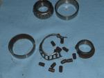
After soaking all day with CRC the stem came out easily with a few good whacks on top of the cap. I thought the top bearing was bad until I saw the bottom one I pulled the rubber seal out first so it didn't get too chewed up and found a small cold chisel had just the right taper to pry the old bearing off. The outer shells popped out quite easily with the aid of a punch. I wrecked the cage getting the bearing off, the rollers hadn't seen grease in quite a while. Tapped the new outer races in with a plastic hammer then used the holding nut to wind the new bearings back on. I couldn't find a torque setting for the bearing nut so I tightened it up to about 20 lb as I would a car wheel bearing. All told it took me about 8 hours, with the right tools it would have gone much quicker. Cost $60 including a courier for the bearings, money well spent.
-
No, I havent tried again, will give it a tap tonight to see if the penetrating oil worked. The bearing supplier was too hard to get to without wheels, they couriered them over a few hours after I called. I hope the other bearings on the bike are so easy to get. No excuse now. I agree, dropping the forks will make it easier. Thanks Guys Roy
-
The bearing on top is a FAG 30205A I called the local bearing supplier, he said yes, that's a standard metric taper roller, they have the Timken equivalent $19.40 each. I'll pick up a couple on the way home Then the fun will start Thanks Everyone Roy
-
Thanks Guys. I screwed the chrome cap back on and gave it several heavy whacks with a plastic mallet I will soak it in penetrating oil and have another go tonight, perhaps use a brass drift so I can bash it with a steel persuader. Are both the upper and lower bearings the same part No? The upper looks like a pretty stock tapered roller.
-
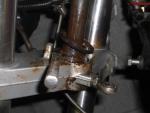
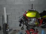
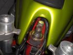
Ok, I have been noticing a little stickiness in the steering so I thought I would pull it apart and inspect the bearings. Once I figured out there were a couple of screws clamping the clip-ons to the top triple clamp it came off easy however I am unable to drop the bottom clamp down, it seems to be jambed in the top tapered roller. I took the weight off the front wheel and rapped it pretty hard on top of the retaining nut with a hammer but no joy. Is it normally hard to slide the assembly apart. Rusty eh! What's the procedure? Thanks in advance Roy
-
I always put an arrow on the rim, sometimes it's not easy to tell which way they are supposed to rotate, especially the front.
-
Perhaps fasten a magnet inside the sump to pick up any loose particles not taken out in the flush process. I used to have the same problem with an old Vincent, I never saw any ill effects from the metal floating around I suspect the particles are too fine to cause damage.
-
Coming out of the voltage regulator there's a pair of wires Black & White The Black wire is the Voltage reference the White one is for the charge light. If you unplug the wires and turn on the key you should be able to measure 12V on the white wire (loom side) and if you ground that wire it will make the light go. If you don't detect 12V either the lamp is burnt out or there isn't one. If the light works when you ground the white wire but never works normally it's possible the switch in the reg is burnt out. Don't worry about it as long as the bike is charging, the later bikes don't have a light
-
It vibrated off to let you know it's time to clean the contacts.
-
That is an excellent write up. I now carry a spare spring so I know mine will never break
-
Is there pressure on the lever like it's lifting or just go to the bar with no back-pressure? If it's the former, perhaps it's stuck to the flywheel If latter you must still have air in there.


