-
Posts
5,002 -
Joined
-
Last visited
-
Days Won
257
Content Type
Profiles
Forums
Events
Gallery
Community Map
Everything posted by Lucky Phil
-
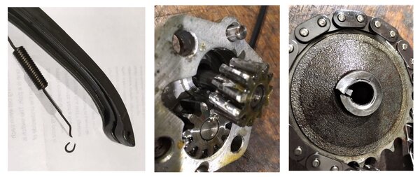
Here's an interesting image of a 1 year old blade style tensioner failure. Nasty collateral. Ciao
-
This, race stands at the back and a scissor jack. The wooden part is a dedicated engine holder which isn't totally necessary. Ciao
-
Well I have a decent sized metal lathe and various other stuff but I dont have a Mill. My closest friend who passes away recently had a full engineering workshop and more importantly the skills on the machines to go with them so I was spoiled for that really. I've just spent the last little while hand digging and jack hammering 18 tons of dirt and rock from under my house which adjoins my garage so when that's concreted and I can move the bikes in there along with storage stuff that takes up room at present and I'll buy myself a Mill and a workshop press and metal bandsaw. Learning how to properly use the mill will be my next mission after that. I've got crankcases and cylinders to bore out:) Ciao
-
I have one of these. Only hassle on the V11 is I need to disconnect the shift lever to use it. Other than that it's perfect. I ordered mine direct from Germany. Make sure you order the sockets with it unless you have a few old ones lying around. Ciao
-
And that's Precisely how the universe and life operates. Einstein's theory of relativity or as he himself explained it for mere mortals " “Put your hand on a hot stove for a minute, and it seems like an hour. Sit with a pretty girl for an hour, and it seems like a minute. That's relativity.” OR, at 67, 10 minutes cleaning header pipes seems to take a day but at 37 it's done in the blink of an eye. That my friends is relativity. Ciao
-
I've run Mobil1 0W-40 full synth group4 oil since day 1 on the original engine and it's never put any oil at all in the airbox. Ciao
-
Haven't you just had the engine rebuilt docc? No need for this if the rings seal well. where did the original hose vent to in the airbox? surely on the engine side of the filter. Did it have a reed valve in the original vent line? Ciao
-
Venting the crankcases into the airbox is perfectly rational. It's been done on WSB engines for at least 35 years. Generally only an issue if your engines got ring seal problems or the original design was really bad or you've taken a pedestrian grocery getter engine and tried to make it a race engine. Ciao
-
In practice it's not generally as bad as you think. A vent to atmosphere has been illegal for probably 40 years or more due to emission regs so it feeds to the airbox to be burned. Ciao
-
So from the Video the light seems to show the alternator not putting out above battery voltage? is that right? Doesn't the V11 alternator normally put out better than battery voltage at idle? I can't remember. Ciao
-
Interesting. Go to 6:45 for stainless exhausts. Ciao
-
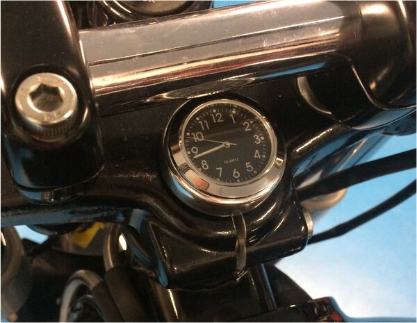
I think that there's not that many options on the V11 to mount that particular clock size in a position that looks neat and tidy. The spot I chose was a bit of a last resort. You can of course just use double sided 1mm thick tape but the domed top on the triple clamp even makes that a little difficult without turning it flat. On my Interceptor I just used the tape mount system although the top nut is pretty flat on that. Ciao
-
From the album: lucky phils V11
-
I was worried someone might ask this. I wanted the clock mounted some other way than a Velcro sticky pad or a double sided pad so I made up the following. This aluminium plug is a slight interference fit in the steering stem tube and is tapped in with some locktite on it to the required depth. The cap screw in the ctr is held in place by a rubber oring so it doesn't fall out when the clock isn't installed. So the cap screw head faces downwards and can be accessed from the bottom of the lower triple clamp up the hollow centre with quarter drive extensions and a 3mm allen head bit. So because you cant get a single long extension up the steering stem tube with the front wheel on you feed 4 short extensions up there as you go. The bit holder on the end has a collar I made to centralise the holder in the centre of the tube so its a simple task of feeding the extensions up the tube and connecting them 1 at a time and when the 3mm bit arrives at the allen head screw just twist it until it drops into the head. Simple and easy as the tool is centred and all you need to do is apply upward pressure and rotate until it engages. With the triple crown nut I machined it down until it was 1mm above flush with the top of the clamp and drilled out the std hex hole round to locate the spigot on the back face of the clock. With the hex drilled out you need a way to install and tighten the top nut now so I drilled 2x 3mm holes which you use a pin wrench on. The pin wrench is the small brass tool in the image above. The object was to have the clock as close to the top surface of the triple clamp as possible but the holding force of the fixing screw was taken by the spigot on the back of the clock so the fixing screw wasn't trying the pull the spigot out the back of the clock rear cover. So here it is ready to slip the clock into the locating hole with one hand and with the other on the ratchet and extensions tighten it down. Easier to do than it sounds. If you had the front wheel and fender off it would just need 1, 12" 1/4 drive extension and the ratchet. Yes I know, sanity is in short supply here. Ciao
-
You might be very surprised at the lack of science put into the mapping and how loose the process is. One particular late model Guzzi when you look into the software it's obvious they started with a Ducati map because it's notated in the ID details. They didn't even bother to change it as only people digging deep into the software would find it. So you go to WM and want a map for your latest model and they just dig out maps from another customer with a similar engine design and capacity and start there. Fair enough but you do wonder sometimes how interested they really get in making it run really nicely. I also had a couple of Triumphs T595's back in the late 90's and they ran the French Sagem system. The factory released plenty of software updates to correct things like random stalling when stopping at the lights and other stuff. I thought it must be terribly hard to rectify this stuff then my friend installed a Motec unit on a customers bike and had the Triumph running and carburetting absolutely perfectly after about 30 min on the dyno. So an injection system manufacturer and a motorcycle manufacturer couldn't do what a talented guy in his own business could achieve in 30min. Sometimes the big wheels turn so slowly they just grind to a stop. Ciao
-
I just went and looked at a std v11 2000 fuel and ignition maps and one interesting thing is around that RPM and probable throttle opening there is a large step in the ignition advance. So 2700-3200 rpm and 4.2-5.2 deg throttle which is kind of in the area of issue. The advance change is interpolated between these cells of course and maybe I'm wrong but possibly this area of change combined with engine temp and OAT play a part. If I still had the 2 valve fitted I could have a play but of course when you want it to hickup it never does. Ciao


